Rotor for permanently energised electrical machine, with support structure

A technology of permanent magnets and rotors, applied in the direction of magnetic circuit rotating parts, magnetic circuit shape/style/structure, magnetic circuit characterized by magnetic materials, etc., can solve the problem of unfavorable distribution of mechanical stress of rotor core, magnetic flux or Insufficient magnetic field strength and other problems, to achieve the effect of large magnetic impedance

Pending Publication Date: 2021-07-23
BAYERISCHE MOTOREN WERKE AG
View PDF21 Cites 0 Cited by
  • Summary
  • Abstract
  • Description
  • Claims
  • Application Information

AI Technical Summary

Problems solved by technology

Although the air bridge between the permanent magnet parts leads to a reduction of the leakage flux, this air bridge leads to the fact that the magnetic flux or the field strength can only be dissipated insufficiently if an active short circuit is introduced into the machine.
Furthermore, air bridges lead to an unfavorable distribution of mechanical stresses in the rotor core

Method used


Image

  • Rotor for permanently energised electrical machine, with support structure

Examples


Embodiment Construction

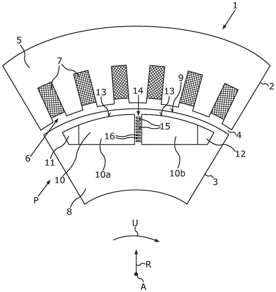
[0023] exist figure 1 The permanent magnet-excited electric machine 1 shown in FIG. 1 can be designed, for example, as a traction motor of an electrically driven motor vehicle, not shown here. The electric machine 1 comprises a stator 2 and a rotor 3 mounted rotatably about an axis of rotation A relative to the stator 2 . The stator 2 and the rotor 3 are arranged at a distance from one another, forming an air gap 4 . The stator 2 has a stator lamination stack 5 with a plurality of grooves 6 arranged distributed in the circumferential direction U, in which grooves are arranged an energizable winding 7 of the stator 2 , said energizable Windings are used to generate a rotating magnetic field. The rotor 3 can be excited to rotate about the axis of rotation A by means of this rotating magnetic field.

[0024] The rotor 3 has at least two rotor poles P, wherein here, for example, one rotor pole P in the form of a magnetic north pole is shown. Adjacent to the magnetic north pole...


PUM


Abstract

The invention relates to a rotor (3) for a permanently energised electrical machine (1) comprising: at least two rotor poles (P) arranged next to one another in the circumferential direction (U); a rotor iron core (8); and a permanent magnet assembly embedded in the rotor iron core (8), for generating a magnetic air-gap flux density, the assembly having at least one permanent magnet (10) per rotor pole (P) and said permanent magnet being divided into at least two permanent magnet parts (10a, 10b), wherein a crosspiece (14) is arranged between the at least two permanent magnet parts (10a, 10b) of a permanent magnet (10), which crosspiece separates two hollow spaces (11, 12) for receiving the permanent magnet parts (10a, 10b) and has magnetically conductive support sections (15) for increasing a mechanical stiffness of the rotor iron core (8) and for discharging external magnetic fluxes in the event of an active short circuit introduced into the electrical machine (1), and magnetically insulating flux-blocking sections (16) for reducing magnetic leakage fluxes. The invention also relates to an electrical machine and to a motor vehicle.

Description

technical field [0001] The invention relates to a rotor for an electrical machine excited with permanent magnets, the rotor having at least two rotor poles arranged next to each other in the circumferential direction. The rotor has a rotor core and an arrangement of permanent magnets embedded in the rotor core for generating an air-gap flux density in an air gap of the electric machine adjacent to the rotor iron outside of the core. For each rotor pole, the permanent magnet arrangement has at least one permanent magnet divided into two permanent magnet parts. The invention also relates to an electric machine excited with permanent magnets and to a motor vehicle. Background technique [0002] This article focuses on electric machines excited with permanent magnets for motor vehicles. Such an electric machine can be used, for example, as a drive machine for an electrically driveable motor vehicle, that is to say an electric vehicle or a hybrid vehicle. An electric machine ...

Claims


Application Information

Patent Timeline
Patent Type & Authority Applications(China)
IPC IPC(8): H02K1/27
CPCH02K1/276H02K1/02H02K1/2773H02K2201/03
Inventor N·伯查德特
Owner BAYERISCHE MOTOREN WERKE AG
Why Eureka
Try Eureka