Unlock instant, AI-driven research and patent intelligence for your innovation.
A livestock feeding device that reduces waste and facilitates collection
What is Al technical title?
Al technical title is built by PatSnap Al team. It summarizes the technical point description of the patent document.
A livestock and feeding trough technology, applied in the field of livestock breeding, can solve the problem that the feed is easy to be pushed out by the livestock, and achieve the effects of increasing contact, facilitating collection, and reducing waste
Active Publication Date: 2021-07-02
SHANDONG UNIV OF TECH
View PDF7 Cites 0 Cited by
Summary
Abstract
Description
Claims
Application Information
AI Technical Summary
This helps you quickly interpret patents by identifying the three key elements:
Problems solved by technology
Method used
Benefits of technology
Problems solved by technology
[0004] The present invention aims at the technical defects of the prior art, and provides a livestock feeding device that reduces waste and is easy to collect, so as to solve the technical problem in the prior art that the feed in the conventional feeding trough is easily pushed out by the livestock
Method used
Image
Click on the blue label to locate the original text in one second.
Reading with bidirectional positioning of images and text.
Examples
Embodiment 1
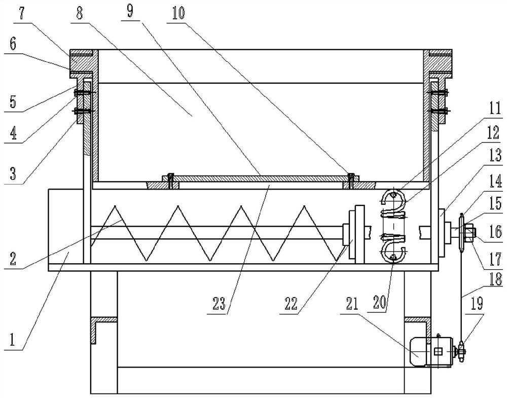
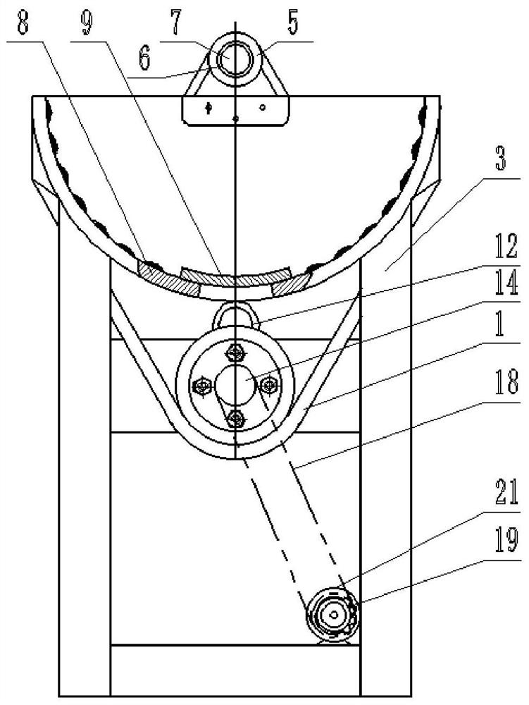
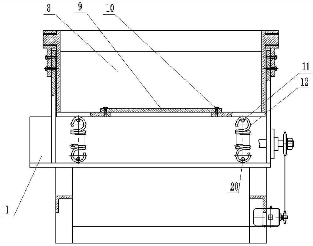
[0035] A livestock feeding device that reduces waste and facilitates collection, such as Figure 1~4 As shown, it includes auger tank 1, auger 2, bracket 3, bolt 4, upper bearing seat 5, sliding bearing 6, tank hinge shaft head 7, feeding trough 8, cover plate 9, round head screw 10, Upper holder 11, spring 12, right bearing holder 13, large sprocket 14, auger shaft 15, washer 16, nut 17, chain 18, small sprocket 19, lower holder 20, motor 21, left bearing holder 22, The discharge port 23 and the protrusion 24, wherein the auger tank body 1 is fixedly connected to the middle part of the support 3, the upper bearing seat 5 is fixedly connected to the top of the support 3 by bolts 4, and the upper bearing seat 5 is fixedly connected with a sliding bearing 6 , on both sides of the feeding trough 8, there are tank hinge shaft heads 7, and the tank body hinge shaft heads 7 are connected to the sliding bearing 6; there is a discharge port 23 at the lower end of the feeding tank 8, a...
Embodiment 2
[0038] A livestock feeding device that reduces waste and facilitates collection, such as Figure 1~4 As shown, it includes auger tank 1, auger 2, bracket 3, bolt 4, upper bearing seat 5, sliding bearing 6, tank hinge shaft head 7, feeding trough 8, cover plate 9, round head screw 10, Upper holder 11, spring 12, right bearing holder 13, large sprocket 14, auger shaft 15, washer 16, nut 17, chain 18, small sprocket 19, lower holder 20, motor 21, left bearing holder 22, The discharge port 23 and the protrusion 24, wherein the auger tank body 1 is fixedly connected to the middle part of the support 3, the upper bearing seat 5 is fixedly connected to the top of the support 3 by bolts 4, and the upper bearing seat 5 is fixedly connected with a sliding bearing 6 , on both sides of the feeding trough 8, there are tank hinge shaft heads 7, and the tank body hinge shaft heads 7 are connected to the sliding bearing 6; there is a discharge port 23 at the lower end of the feeding tank 8, a...
PUM
Abstract
The present invention provides a livestock feeding device that reduces waste and facilitates collection. In this technical solution, the feeding trough is carried on a horizontal rotating shaft, and the position of the rotating shaft is higher than the axis of the arc surface of the feeding trough. With its own gravity and the pulling force of the spring, when the feed trough rotates under the push of the livestock, the feed can immediately return to its position to prevent the feed from spilling out. In addition, the present invention adds protrusions distributed in an array on the inner wall of the feeding trough, which can increase the contact between the residual feed and the outside air to a certain extent, and alleviate the problem of adhesion; in addition, the present invention adds A closeable discharge port is provided, and an auger is set at the lower end of the discharge port. When the feeding trough needs to be cleaned, the residual feed can be manually brushed to the discharge port, and thus falls into the lower auger, and then the agitator is turned on. Long, push it to the outside, so as to complete the cleaning work conveniently.
Description
technical field [0001] The invention relates to the technical field of animal husbandry, in particular to a livestock feeding device that reduces waste and facilitates collection. Background technique [0002] In the breeding process of large livestock, feeding troughs are usually used to hold feed and serve as containers for livestock to eat. Conventional feeding troughs have no special design at present, and are only fixedly arranged at a position that livestock can touch. This mode has a long history, but there are many defects in the use process. [0003] Since livestock feed has the habit of tending to concentrated feed (that is, to select the concentrated feed in the mixed feed, such as corn flour, bran, etc.), the feed is often pushed out of the trough, resulting in serious waste. In addition, some feed remains in the trough after the livestock feed. Due to the smooth structure of the conventional inner wall, the residual feed is easy to adhere to the inner wall, whi...
Claims
Application Information
Patent Timeline
Application Date:The date an application was filed.
Publication Date:The date a patent or application was officially published.
First Publication Date:The earliest publication date of a patent with the same application number.
Issue Date:Publication date of the patent grant document.
PCT Entry Date:The Entry date of PCT National Phase.
Estimated Expiry Date:The statutory expiry date of a patent right according to the Patent Law, and it is the longest term of protection that the patent right can achieve without the termination of the patent right due to other reasons(Term extension factor has been taken into account ).
Invalid Date:Actual expiry date is based on effective date or publication date of legal transaction data of invalid patent.
