
Knee joint prosthesis testing system and testing method

A test system, knee joint technology, applied in the direction of joint implants, joint implants, prostheses, etc., can solve the problem of complex control systems, without considering the magnitude of the reaction force of the prosthesis, and the intelligent prosthetic test system is not competent for intelligent prosthetic testing Need and other questions

Active Publication Date: 2020-08-25
JILIN UNIV
View PDF5 Cites 5 Cited by
  • Summary
  • Abstract
  • Description
  • Claims
  • Application Information

AI Technical Summary

Problems solved by technology

[0003] However, the testing of artificial limbs has become one of the problems that limit the development of intelligent artificial limbs. At present, most artificial limb research and development institutions still use the method of recruiting amputees to wear finished artificial limbs to test artificial limbs. The design and manufacture of intelligent artificial limbs are different from traditional passive mechanical artificial limbs. A complex electromechanical system that integrates machinery, electricity, or machinery, electricity, and fluid. Traditional testing methods are not suitable for testing intelligent prosthetics.
[0004] Existing smart prosthesis test systems can only perform horizontal walking tests. During the test, either the ground reaction force received by the prosthesis is not considered accurate, or the ground reaction force indirectly controls the foot through the control system to control the up and down motion of the hip joint. It is produced with a treadmill, but this control system is very complicated and difficult to implement. In addition, the existing intelligent prosthetic test system is not capable of testing the intelligent prosthetic up and down stairs and up and downhill.

Method used


Image

  • Knee joint prosthesis testing system and testing method
  • Knee joint prosthesis testing system and testing method
  • Knee joint prosthesis testing system and testing method

Examples


Embodiment Construction

[0059] The present invention will be described in further detail below in conjunction with the accompanying drawings.

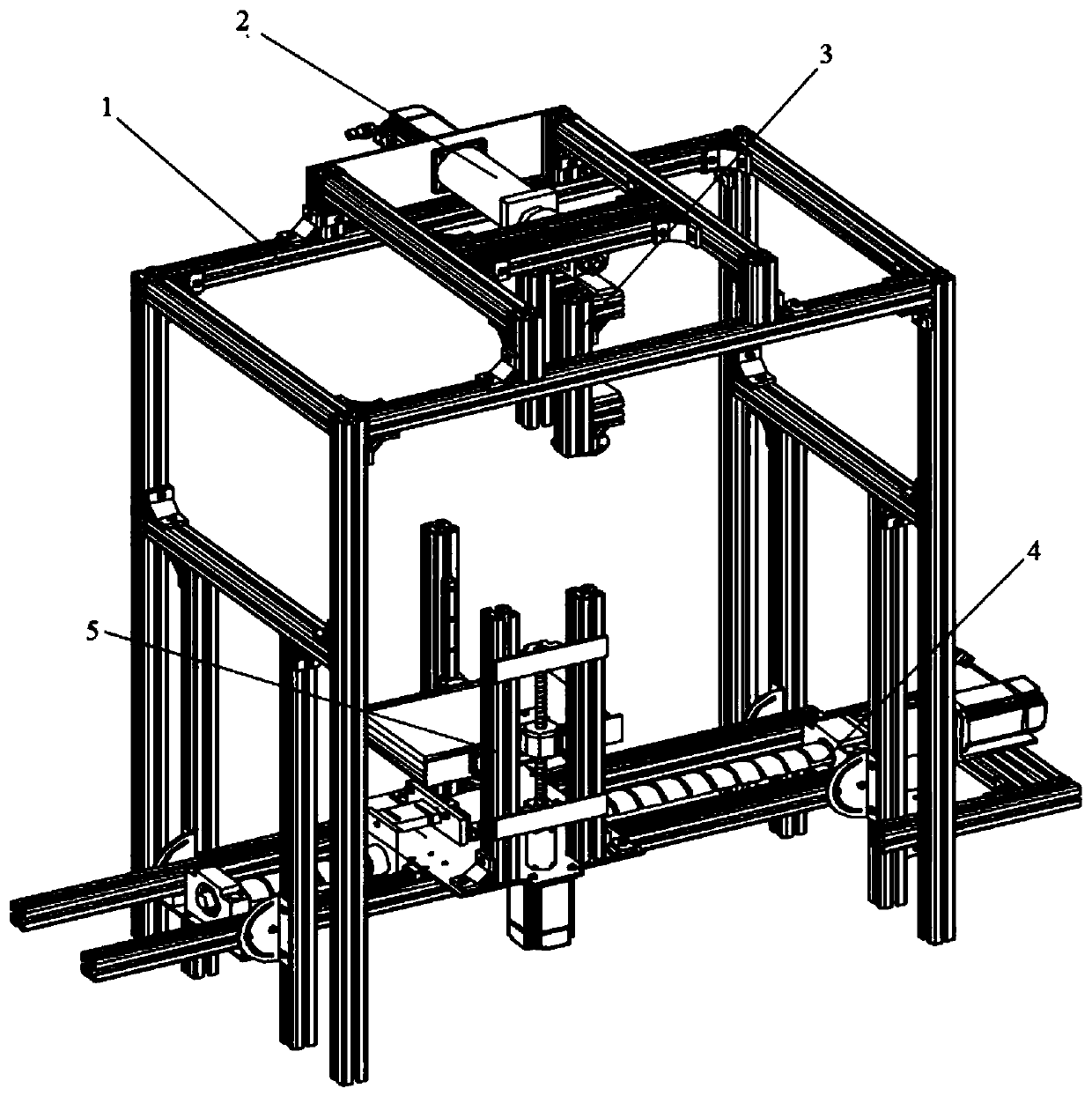
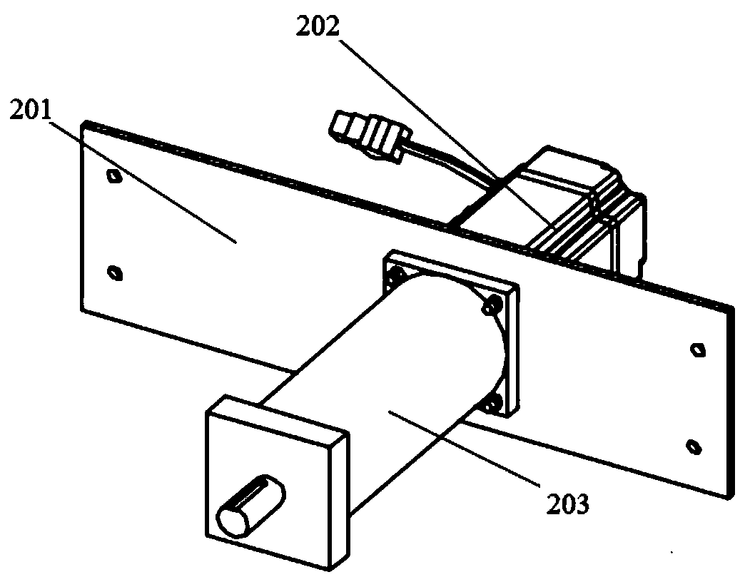
[0060] A knee prosthesis testing system such as figure 1 , Figure 9 and Figure 10 As shown, it includes frame 1, hip joint driving system 2, bionic thigh 3, horizontal motion module 4 and ground reaction force module 5; wherein hip joint driving system 2 is installed on the top of frame 1, and horizontal motion module 4 is installed under frame 1, The ground reaction force module 5 is installed above the horizontal movement module 4, and can move back and forth along the horizontal movement module 4 under the drive of the horizontal movement module 4;

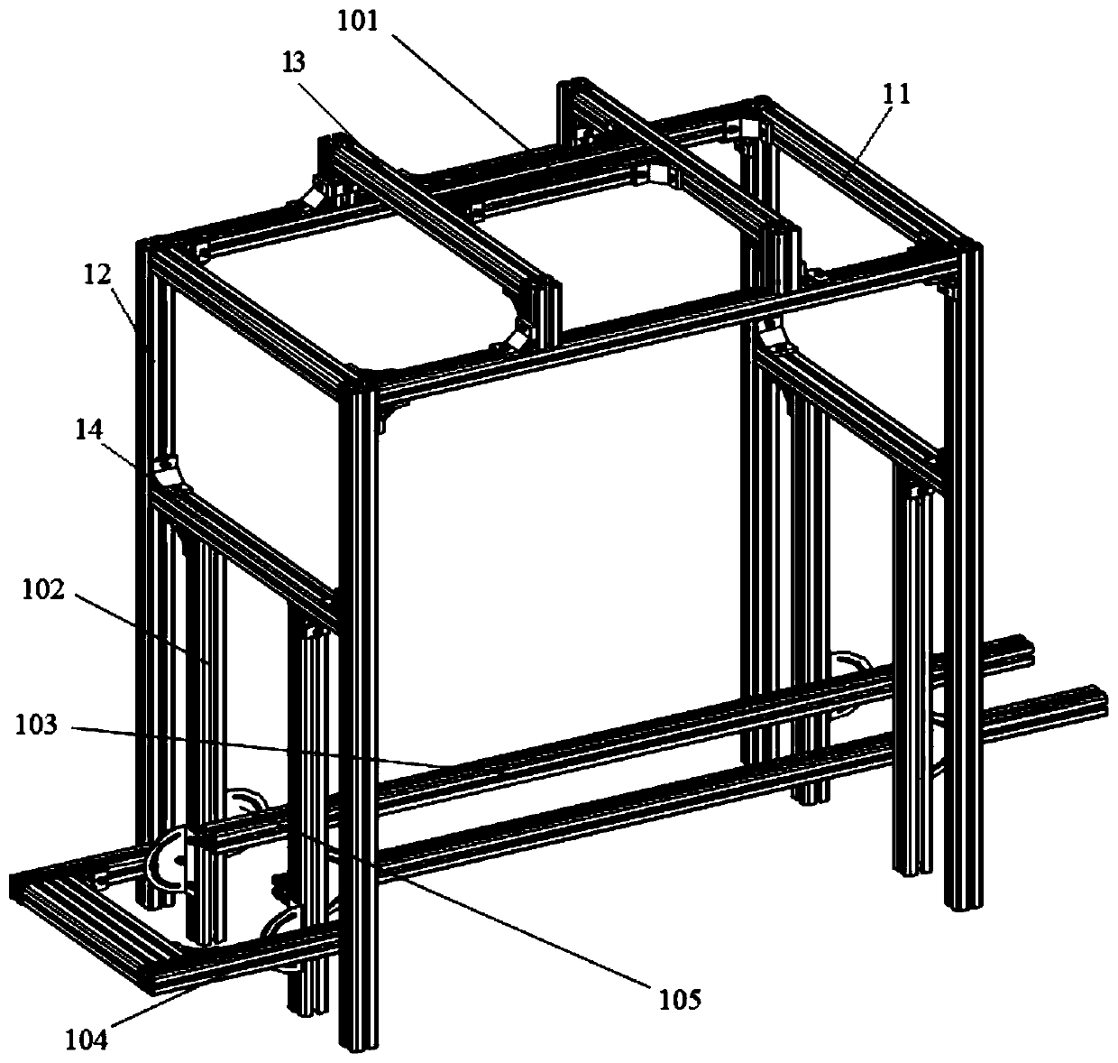
[0061] like figure 2 As shown, the frame 1 is spliced ​​by aluminum alloy profiles, and the connection between the rods is realized through corner codes. Two portal frames 13 are fixed on the top of the frame 1, and the bionic thigh mounting rod 101 is fixed on the two portal frames 13. between them, an...


PUM


Abstract

The invention belongs to the technical field of prosthetic testing devices, and particularly relates to a knee joint prosthesis testing system and a testing method. The testing system comprises a hipjoint drive system, a bionic thigh, a frame, a horizontal movement module and a ground reaction force module. According to the prosthesis testing platform, movement of the stump of an amputee can be simulated in a gait cycle by an automatic control system, ground reaction force is provided for the tested prosthesis, and an accurate testing environment is provided for the intelligent knee joint assembled at a joint by matching a movement curve of real human lower limbs. Compared with the previous prosthesis testing equipment, the test platform can actively provide the ground reaction force forthe prosthesis, and input of the ground reaction force in the prosthesis testing process is more accurate; and prosthesis testing in the circumstances of horizontal walking at different speeds, goingup and down the slope, going up and down stairs and the like can be achieved.

Description

technical field [0001] The invention belongs to the technical field of prosthetic limb testing devices, and in particular relates to a knee joint prosthetic testing system and testing method. Background technique [0002] Wearing prosthetic limbs is the main means of solving many mobility impairment patients. In recent years, intelligent prosthetics that can help patients realize functions such as going up and down stairs, going up and down slopes, sitting up and down, and brisk walking have been especially favored by people. The so-called intelligent prosthesis refers to the use of various sensor information fusion, microprocessor control and other technologies to enable it to move according to the user's intention and have the ability to actively adapt to changes in external conditions. [0003] However, the testing of artificial limbs has become one of the problems that limit the development of intelligent artificial limbs. At present, most artificial limb research and d...

Claims


Application Information

Patent Timeline
IPC IPC(8): A61F2/46A61F2/76
CPCA61F2/4684A61F2/76A61F2002/7695
Inventor 任雷王同建付德龙刘春宝陈秋
Owner JILIN UNIV
Learn More