Multi-directional rotary forming hydraulic machine

A technology of rotary forming and hydraulic press, which is applied to forging presses, forging presses, forging press driving devices, etc., can solve the problems of low processing efficiency and achieve the effect of increasing the processing range and precise and efficient processing

Active Publication Date: 2020-08-25
YANSHAN UNIV
View PDF6 Cites 2 Cited by
  • Summary
  • Abstract
  • Description
  • Claims
  • Application Information

AI Technical Summary

Problems solved by technology

[0002] The multi-directional die forging process combines the advantages of die forging and extrusion technology, and overcomes the limitations and low efficiency of traditional forging equipment processing technology.

Method used


Image

  • Multi-directional rotary forming hydraulic machine
  • Multi-directional rotary forming hydraulic machine
  • Multi-directional rotary forming hydraulic machine

Examples


Embodiment 1

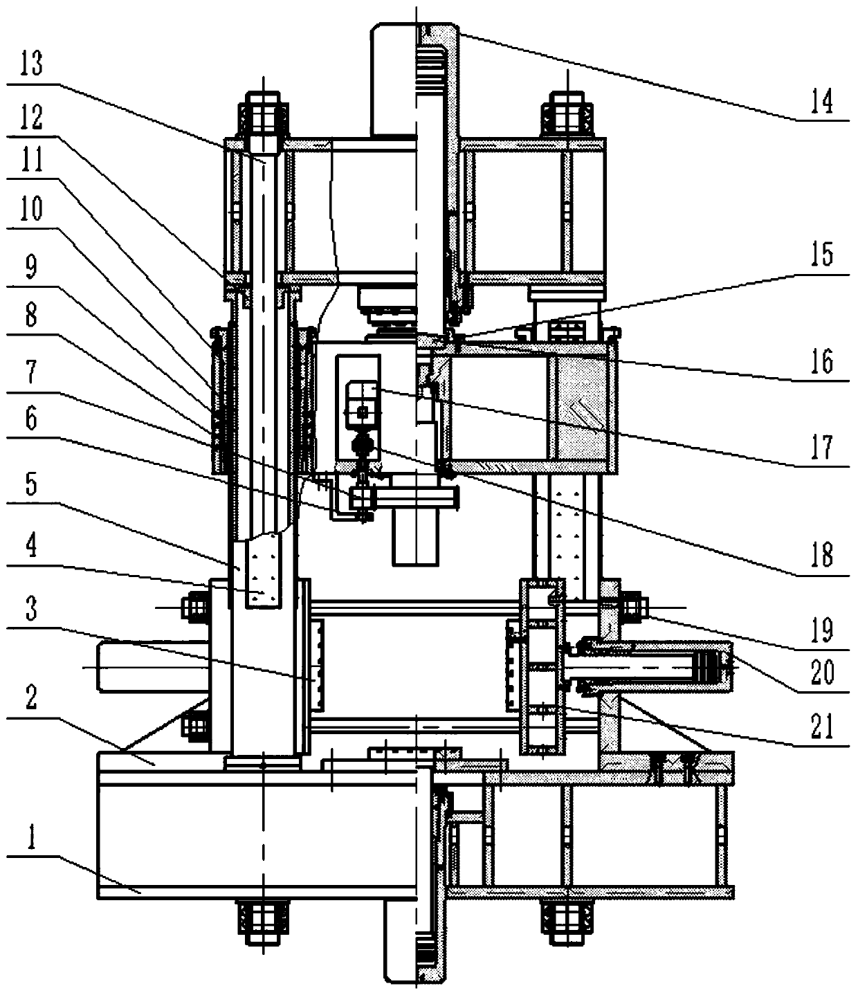
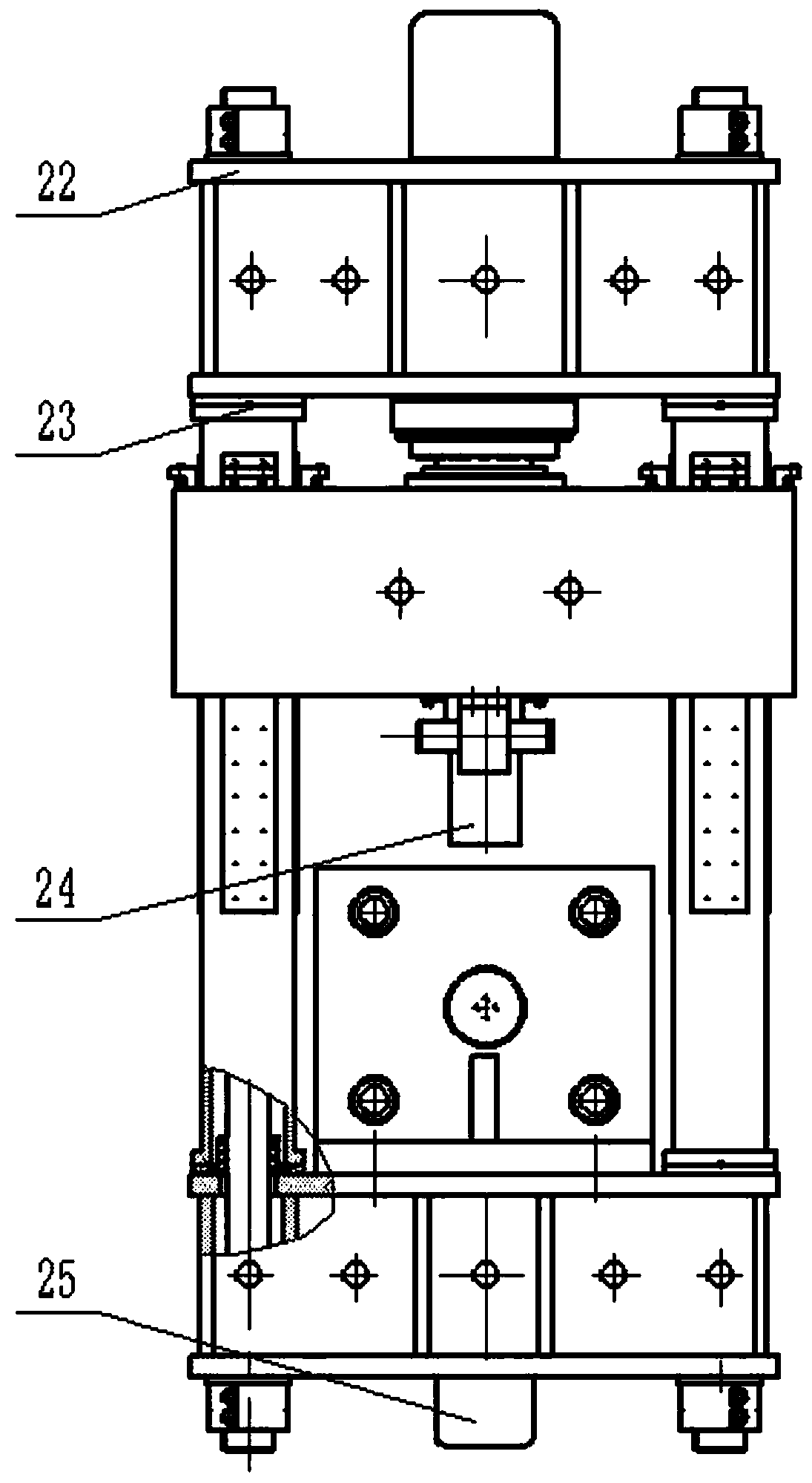
[0029] Such as Figure 1-6 As shown, this embodiment provides a multi-directional rotary forming hydraulic machine, which mainly includes a square column 5, a large tie rod 13, a small tie rod 19, an upper beam 22, a main piston cylinder 14, a movable beam 11, a large gear shaft 24, and a pinion shaft 7. Three-phase asynchronous motor 17, lower beam 1, bottom piston cylinder 25, side beam 2, side piston cylinder 20, side movable beam 21, workbench 3.

[0030] In this embodiment, the square column, the large tie rods, the small tie rods, the upper beam, the movable beam, the lower beam, the side beams, and the side movable beam constitute the frame structure of the hydraulic machine. The upper beam is located on the upper part of the square column and is rigidly connected with the square column. The main piston cylinder is installed on the upper beam; the movable beam is located below the upper beam and is rigidly connected with the piston rod of the main piston cylinder. A th...


PUM


Abstract

The invention discloses a multi-directional rotary forming hydraulic machine. The multi-directional rotary forming hydraulic machine comprises a frame structure, a main piston cylinder, a large gear shaft, a three-phase asynchronous motor, a bottom piston cylinder, side piston cylinders and a worktable; the frame structure comprises a square stand column, an upper cross beam, a movable cross beamand a lower cross beam, the upper cross beam is installed on the upper part of the square stand column, and the main piston cylinder is installed on the upper cross beam; and the bottom end of the main piston cylinder is connected with the movable cross beam, and the movable cross beam is slidably arranged on the square stand column. A large gear shaft is arranged under the movable cross beam, andthe movable cross beam drives the large gear shaft to move while the three-phase asynchronous motor can drive the large gear shaft to rotate; the bottom piston cylinder is installed on the lower cross beam, and the worktable is arranged at the top of the bottom piston cylinder; two side cross beams are symmetrically arranged on the lower cross beam, the side piston cylinders are installed on theside cross beams, and the worktable is arranged at the output ends of the side piston cylinders. The multi-directional rotary forming hydraulic machine achieves the effect of forming larger parts withsmaller force, the complex parts can be accurately and efficiently machined, and the machining range of a multi-directional die forging hydraulic press is increased.

Description

technical field [0001] The invention relates to the technical field of metal plastic forming equipment manufacturing, in particular to a multi-directional rotary forming hydraulic press. Background technique [0002] The multi-directional die forging process combines the advantages of die forging and extrusion technology, and overcomes the limitations and low efficiency of traditional forging equipment. This process enables the process to process complex parts that are difficult to complete in a general die forging process, improves the utilization rate of materials, improves the stress corrosion resistance of parts in special environments, reduces the amount of subsequent processing, reduces the process flow, and has high dimensional accuracy of forged blanks , dense metallographic structure and other advantages. [0003] Therefore, multi-directional die forging technology and equipment have been developed rapidly at home and abroad. Now it has been extended from the proce...

Claims


Application Information

Patent Timeline
IPC IPC(8): B21J9/02B21J13/04B21J9/12
CPCB21J9/025B21J9/12B21J13/04
Inventor 顾勇飞骆俊廷崔天伦张丽丽张春祥
Owner YANSHAN UNIV
Why Eureka
Try Eureka