Using method of workpiece continuous press mounting device

A technology of pressing device and workpiece, applied in the field of continuous pressing device for workpiece and workpiece assembly and processing, can solve the problems of low degree of automation, safety accidents of workers, difficulty in meeting the needs of large-scale industrial production, etc., and achieves reasonable structural design. Effect

Inactive Publication Date: 2020-08-25
黄明珠
View PDF0 Cites 0 Cited by
  • Summary
  • Abstract
  • Description
  • Claims
  • Application Information

AI Technical Summary

Problems solved by technology

The existing workpiece assembly method is to manually assist the assembly equipment to assemble the workpiece. During the entire assembly process of the workpiece, it is necessary to manually place the workpieces one by one on the assembly equipment for assembly. The assembly efficiency of the workpiece is low, and it is difficult to meet large quantities. Due to the industrial production needs, and during the entire assembly process of the workpiece, the labor intensity of the workers is relatively high. In the process of continuously picking and placing the workpieces, the workers are easily caught by the assembly equipment due to the misoperation of the workers and the fatigue of continuous production and processing. Injury, resulting in production safety accidents of workers
The existing workpiece assembly is difficult to achieve efficient and stable assembly processing, the efficiency and quality of workpiece assembly processing are difficult to be guaranteed, and the automation degree of workpiece assembly processing is low, which cannot meet the needs of processing and use

Method used


Image

  • Using method of workpiece continuous press mounting device
  • Using method of workpiece continuous press mounting device
  • Using method of workpiece continuous press mounting device

Examples


Embodiment Construction

[0014] In order to further describe the present invention, a specific implementation of a continuous press-fitting device for workpieces will be described below with reference to the accompanying drawings. The following embodiments are for explaining the present invention and the present invention is not limited to the following embodiments.

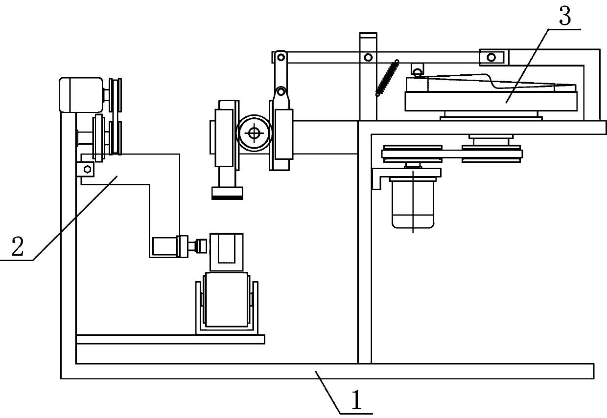
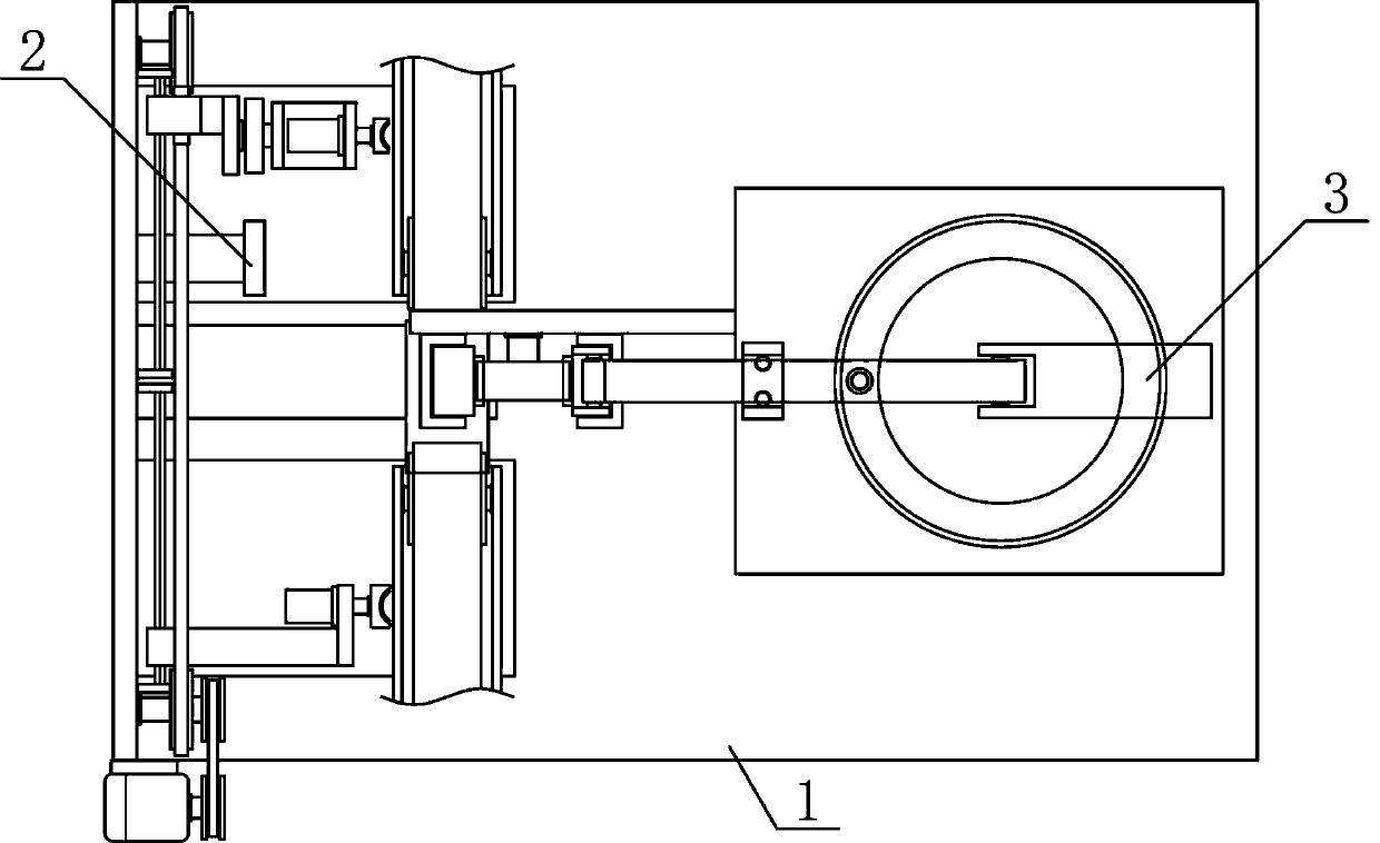
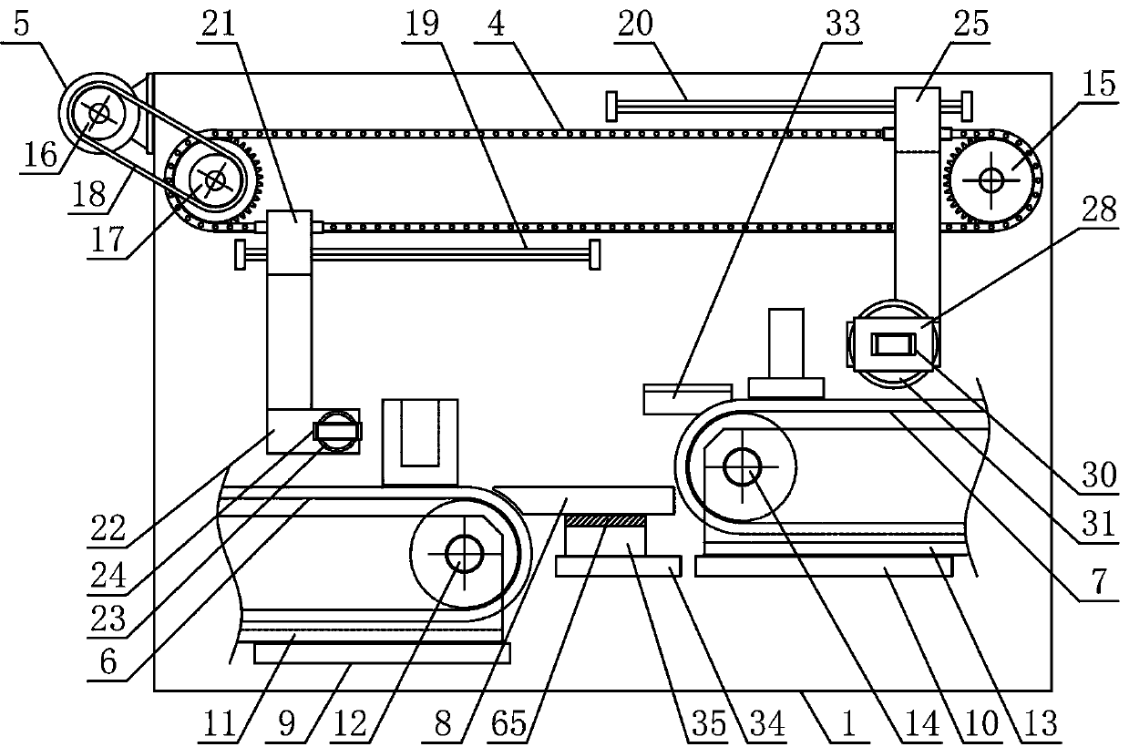
[0015] Such as figure 1 with figure 2 As shown, a continuous workpiece press-fitting device of the present invention includes a workpiece processing support 1, a workpiece transfer mechanism 2 and a workpiece press-fit mechanism 3. The workpiece transfer mechanism 2 and the workpiece press-fit mechanism 3 are arranged in the workpiece processing support 1 in a horizontal direction. Upper side, such as image 3 with Figure 4 As shown, the workpiece transfer mechanism 2 of the present invention includes a material-moving chain 4, a material-moving motor 5, a first conveyor belt 6, a second conveyor belt 7 and a discharge support plate 8. The ...


PUM


Abstract

The invention discloses a using method of a workpiece continuous press mounting device, and belongs to the field of workpiece machining machinery. A workpiece transfer mechanism and a workpiece pressmounting mechanism are sequentially arranged on the upper side of a workpiece machining bracket, a material transfer chain is arranged on one side of the upper part of the workpiece machining bracket,a first adsorption connecting plate is horizontally and fixedly arranged at the output end of a first air cylinder, a second adsorption connecting plate is horizontally and fixedly arranged at the output end of a second air cylinder, a material placing bearing plate is horizontally arranged between a first conveyor belt and a second conveyor belt, an annular guide plate is arranged on the outer side of the upper part of a rotating disc, a rotating pressing rod is arranged on the upper side of the rotating disc, the two sides of a press mounting gear are correspondingly connected with a lifting rack and a press mounting rack in an engaged mode, and a lifting connecting rod is arranged between the rotating pressing rod and the lifting rack. According to the using method, the structural design is reasonable, a workpiece can be conveniently and accurately transferred to a required press mounting station, the workpiece can be stably and efficiently machined by press mounting, the degree ofautomation is high, and the needs of machining and using are met.

Description

Technical field [0001] The invention belongs to the field of workpiece processing machinery and equipment, and in particular relates to a method for using a continuous press-fitting device for workpieces, and is mainly applied to assembly processing of workpieces. Background technique [0002] Mechanical workpieces are single parts that make up machinery and machinery that cannot be separated. It plays an important role in the automation industry. Mechanical workpieces include the connection of parts, supporting parts, lubricating systems and sealing components that play a role in lubrication. Components, components of the transmission system that transmit motion and energy. In the process of producing and processing mechanical workpieces, the workpieces need to be processed separately after the processing steps of die-casting, frosting, and punching. Assembly: Assemble two workpieces into a combined workpiece, so that the assembled workpieces can be conveniently used by subseque...

Claims


Application Information

Patent Timeline
Patent Type & Authority Applications(China)
IPC IPC(8): B23P19/00B23P19/027
CPCB23P19/001B23P19/007B23P19/027
Inventor 黄明珠
Owner 黄明珠
Why Eureka
Try Eureka