Watchcase grinding equipment and application thereof

A watch case and equipment technology, applied in the direction of grinding/polishing equipment, metal processing equipment, grinding machines, etc., can solve the problems that affect the accuracy of watch case grinding, cannot realize automatic grinding, and reduce grinding efficiency

Inactive Publication Date: 2020-08-25
苏州椿桔五金制品有限公司
View PDF8 Cites 6 Cited by
  • Summary
  • Abstract
  • Description
  • Claims
  • Application Information

AI Technical Summary

Problems solved by technology

Grinding the watch case through the abrasive belt, the abrasive belt will loosen during the grinding process, which will affect the grinding accuracy of the watch case, and the abrasive belt needs to be replaced frequently during the grinding process, which reduces the grinding efficiency, and the device cannot Fully automatic grinding

Method used


Image

  • Watchcase grinding equipment and application thereof
  • Watchcase grinding equipment and application thereof

Examples


Embodiment 1

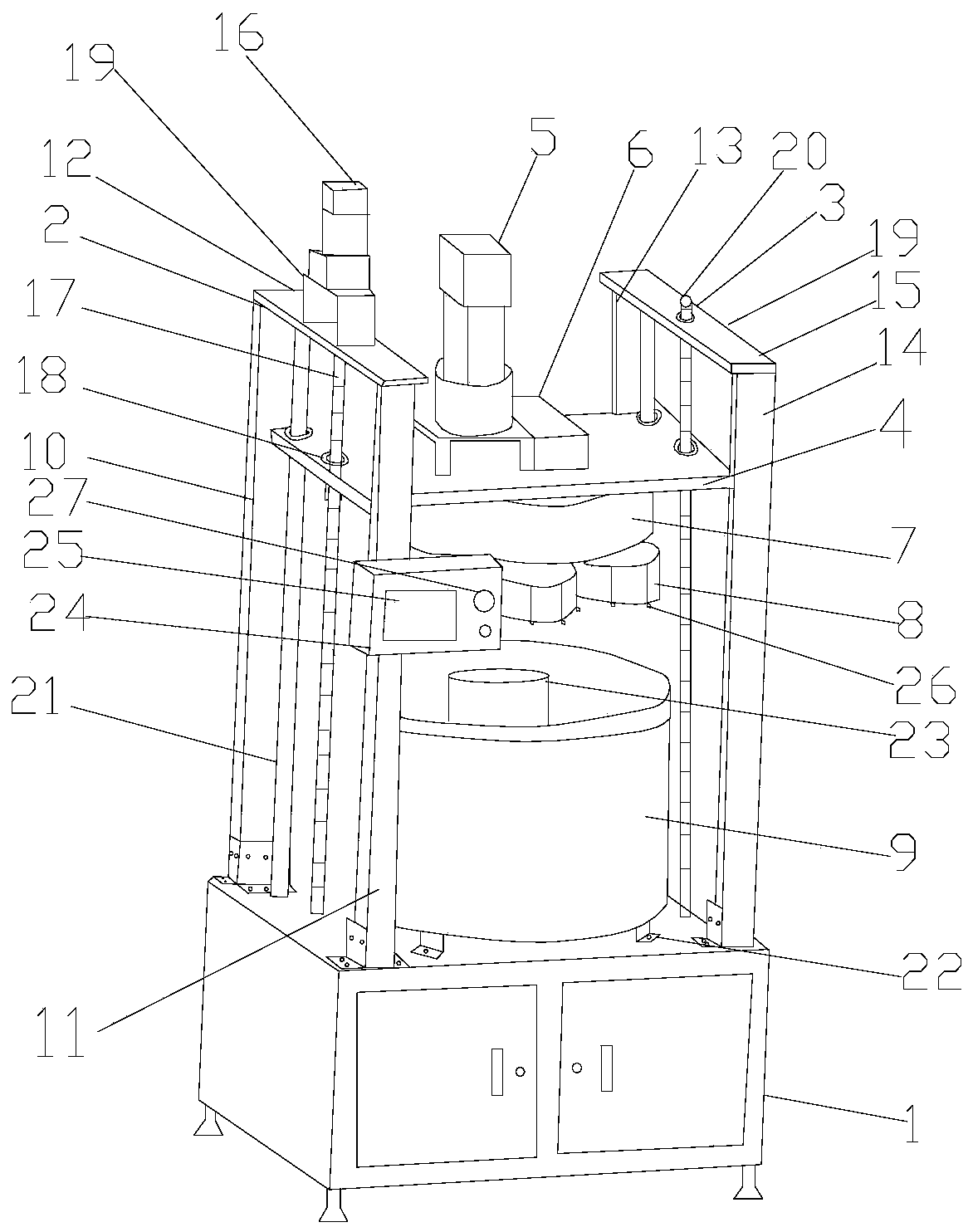
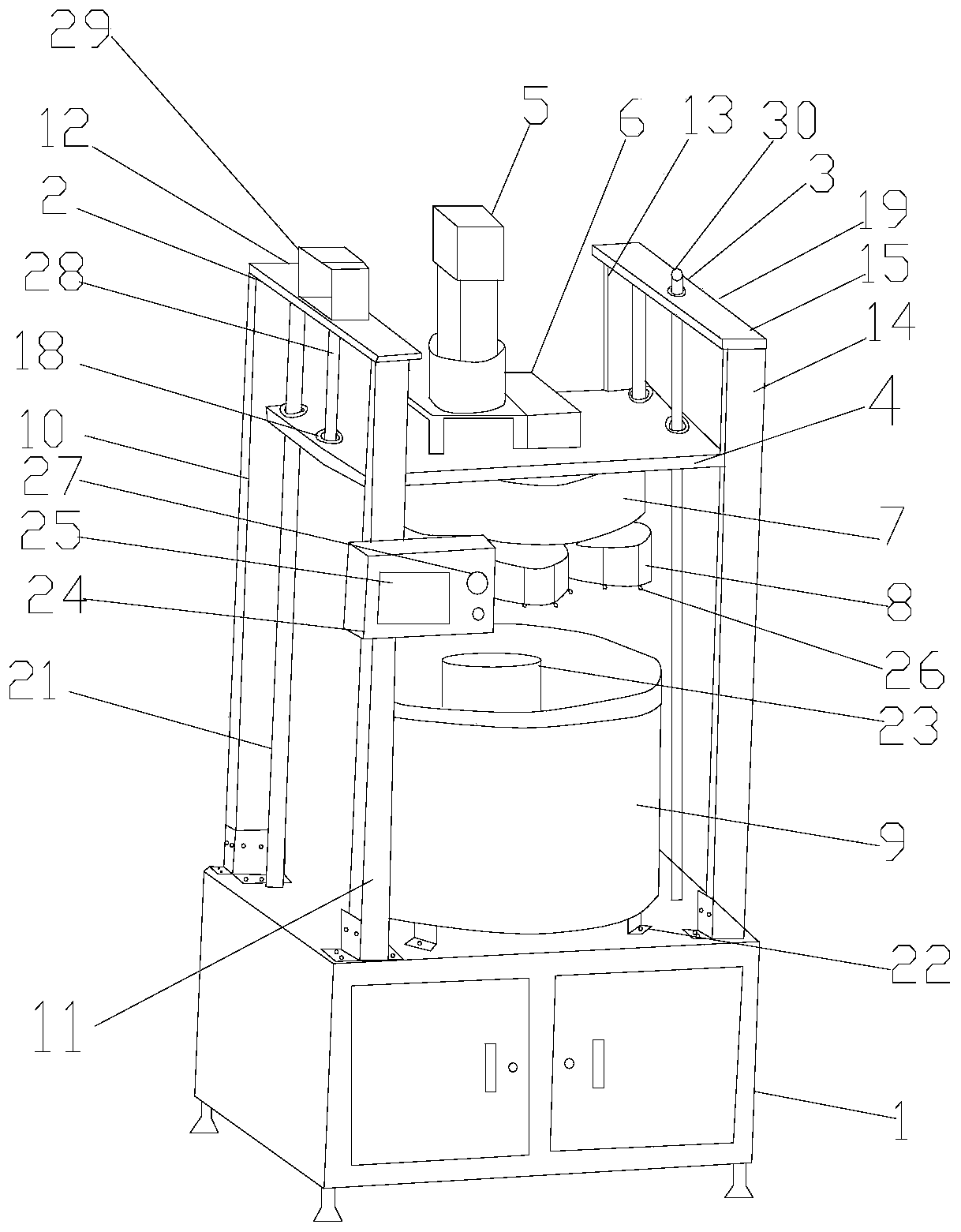
[0038] A watch case grinding equipment, comprising a grinding machine bracket 1, a supporting device installed on the upper part of the grinding machine bracket 1, a grinding device and a first driving device installed on the supporting device, and a container for holding abrasive materials located below the grinding device device, a clamping device 26 for clamping the watch case is installed on the polishing device.

[0039] The support device includes a first support device 2 and a second support device 3 installed above the grinder support, and a support plate 4 between the first support device 2 and the second support device 3 . The structure of the first supporting device 2 is the same as that of the second supporting device 3, and the first supporting device 2 includes a first supporting column 10 connected to the top of the grinder support 1, a second supporting column 11, a connection between the first supporting column 10 and the The first fixed plate 12 of the second...

Embodiment 2

[0046] In this embodiment, only the technical points different from those in Embodiment 1 are stated, and the technical features not described in detail in this embodiment are all the same as those in Embodiment 1. In this embodiment, a second linear stepping motor is installed on the second fixing plate, and the power output end of the second linear stepping motor is connected to the upper end of the second screw rod. There are six second rotating devices in this embodiment. 6 clamping devices are installed on each second rotating device. The bottom of the first receiving tray is fixedly connected with 6 fixing parts, and the fixing parts are connected with the upper part of the grinder support through screws.

Embodiment 3

[0048] In this embodiment, only the technical points different from those in Embodiment 1 are stated, and the technical features not described in detail in this embodiment are all the same as those in Embodiment 1. There are 10 second rotating devices in this embodiment. 10 clamping devices are installed on each second rotating device. The bottom of the first receiving tray is fixedly connected with 10 fixing parts, and the fixing parts are connected with the upper part of the grinding support through screws.


PUM


Abstract

The invention provides watchcase grinding equipment and application thereof. The watchcase grinding equipment comprises a grinder support, a supporting device mounted on the upper portion of the grinder support, a grinding device, a first drive device and a containing device located below the grinding device and used for containing grinding materials, wherein the supporting device and the first drive device are mounted on the supporting device. A clamping device used for clamping a watchcase is mounted on the grinding device. The grinding device is driven by the first drive device to rotate, and therefore the grinding device drives the watchcase to rotate. The supporting device comprises a supporting plate. The watchcase grinding equipment further comprises a second drive device mounted onthe supporting device. The second drive device drives the supporting plate to ascend and descend, and therefore the watchcase is driven to ascend and descend to descend into the containing groove, and the watchcase is in contact with grinding materials; and mutual friction between the watchcase and the grinding materials is achieved while the watchcase rotates, automatic grinding is achieved, andgrinding efficiency is improved. The watchcase grinding equipment is used for grinding of various kinds of metal watchcases.

Description

technical field [0001] The application belongs to the technical field of watch case processing equipment, and in particular relates to watch case grinding equipment and its application. Background technique [0002] The watch case usually refers to the shell part of the main body (head) of the watch, and its material is generally selected from steel, ceramics, plastics, etc., and the steel watch case is the most common. The function of the watch case is to contain and protect the internal components of the watch (movement, dial, hands, etc.), and the parts closely connected with the watch case are: watch mirror, bottom cover, crown, buttons, etc. During the processing of the watch case, it needs to go through processes such as rough turning, fine turning, grinding and polishing. When grinding the case, it is difficult to use automatic grinding due to the irregular shape of the case. Most of the existing watch case grinding is non-automatic grinding with abrasive belts. In ...

Claims


Application Information

Patent Timeline
Patent Type & Authority Applications(China)
IPC IPC(8): B24B31/00B24B27/00B24B31/12B24B41/06B24B47/12B24B47/20
CPCB24B27/0023B24B31/003B24B31/12B24B41/06B24B47/12B24B47/20
Inventor 陈俊余
Owner 苏州椿桔五金制品有限公司
Why Eureka
Try Eureka