Sponge cutting equipment

A sponge cutting and equipment technology, applied in metal processing and other directions, can solve problems such as lack of fixing function and insufficient cutting flatness

Active Publication Date: 2020-08-25
惠州中记家具制造有限公司
View PDF10 Cites 3 Cited by
  • Summary
  • Abstract
  • Description
  • Claims
  • Application Information

AI Technical Summary

Problems solved by technology

[0004] Based on this, it is necessary to provide a sponge cutting device for the technical problem of lack of fixing function to cut flatness

Method used


Image

  • Sponge cutting equipment
  • Sponge cutting equipment
  • Sponge cutting equipment

Examples


Embodiment Construction

[0022] In order to make the above objects, features and advantages of the present invention more comprehensible, specific implementations of the present invention will be described in detail below in conjunction with the accompanying drawings. In the following description, numerous specific details are set forth in order to provide a thorough understanding of the present invention. However, the present invention can be implemented in many other ways different from those described here, and those skilled in the art can make similar improvements without departing from the connotation of the present invention, so the present invention is not limited by the specific embodiments disclosed below.

[0023] In describing the present invention, it should be understood that the terms "center", "longitudinal", "transverse", "length", "width", "thickness", "upper", "lower", "front", " Back", "Left", "Right", "Vertical", "Horizontal", "Top", "Bottom", "Inner", "Outer", "Clockwise", "Counte...


PUM


Abstract

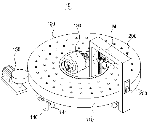
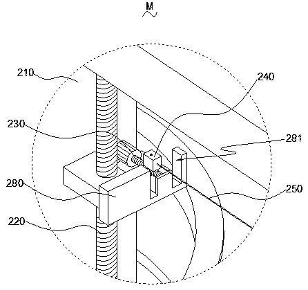
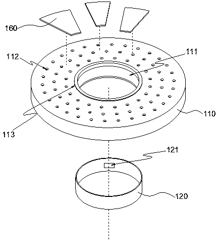
The invention provides sponge cutting equipment. The sponge cutting equipment comprises a transportation mechanism and a cutting mechanism. The transportation mechanism comprises an annular disc base,a side annular plate, an exhaust fan, a plurality of sliding supporting legs and a driving device. An inner cavity groove is formed in the annular disc base and the side annual plate is arranged on the inner cavity groove and is slidably connected with the annular disc base. A plurality of air inducing holes are formed in the top surface of the annular disc base. An air inducing opening is formedin the side annular plate and the air inducing opening communicates with an output end of the exhaust fan. The driving device is connected with the annular disc base in a driving mode. The cutting mechanism comprises a portal frame, two lifting screw rod motors, two reciprocating screw rod motors, two fixed blocks, a cutting wire and a controlling mechanism. The two lifting screw rod motors are arranged on the portal frame, each lifting screw rod motor is connected with one reciprocating screw rod motor in a driving mode, each reciprocating screw rod motor is connected with one fixed block ina driving mode, and the cutting wire is connected with the two fixed blocks respectively. The sponge cutting equipment realizes a function of fixing a sponge to be cut in an adhesive mode, and improves the degree of smooth cutting.

Description

technical field [0001] The invention relates to the technical field of cutting machines, in particular to a sponge cutting device. Background technique [0002] In the process of manufacturing soft furniture such as sofas, sponge pads for matching the type of soft furniture are generally produced accordingly. In order to be able to install with the furniture smoothly, and realize the cooperation with the furniture. In the production process of the sponge pad, the size of the sponge pad is controlled, and the sponge is generally cut by a cutting machine to determine its size. [0003] However, the current sponge cutting equipment lacks a fixing effect on the sponge to be cut, so that the sponge to be cut is easy to move, which leads to inaccurate cutting thickness of the sponge and affects the cutting quality. In addition, the cutting flatness is insufficient, the cut surface of the sponge is relatively rough, and the fineness of the cut surface of the sponge is low. Cont...

Claims


Application Information

Patent Timeline
Patent Type & Authority Applications(China)
IPC IPC(8): B26D1/06B26D1/547B26D5/06B26D5/08B26D7/01B26D7/06B26D7/26
CPCB26D1/06B26D1/547B26D5/06B26D5/08B26D7/01B26D7/018B26D7/06B26D7/2628
Inventor 叶孟霆
Owner 惠州中记家具制造有限公司
Why Eureka
Try Eureka