Eureka AIR delivers breakthrough ideas for toughest innovation challenges, trusted by R&D personnel around the world.

Clamping device for battery of new energy vehicle

A new energy vehicle and clamping device technology, applied in battery pack parts, circuits, electrical components, etc., can solve the problems of inability to clamp the battery, unfavorable battery clamping, etc., and achieve the effect of improving the clamping efficiency

Active Publication Date: 2020-08-25
上海航空发动机制造有限公司
View PDF6 Cites 3 Cited by
  • Summary
  • Abstract
  • Description
  • Claims
  • Application Information

AI Technical Summary

Problems solved by technology

[0002] New energy, also known as unconventional energy, refers to various forms of energy other than traditional energy, and refers to energy that has just begun to be developed and utilized or is being actively researched and yet to be promoted, such as solar energy, geothermal energy, wind energy, ocean energy, biomass energy and Nuclear fusion energy, etc. New energy vehicles are one of the new energy applications. New energy vehicles are composed of many parts, and batteries are one of them. During the processing of batteries, clamping devices are needed to improve their processing efficiency. However, the existing battery clamping device cannot clamp different types of batteries, which is not conducive to the clamping of the battery. Therefore, we propose a new energy vehicle battery clamping device

Method used


Image

  • Clamping device for battery of new energy vehicle
  • Clamping device for battery of new energy vehicle
  • Clamping device for battery of new energy vehicle

Examples


Embodiment Construction

[0016] The following will clearly and completely describe the technical solutions in the embodiments of the present invention with reference to the accompanying drawings in the embodiments of the present invention. Obviously, the described embodiments are only some, not all, embodiments of the present invention. Based on the embodiments of the present invention, all other embodiments obtained by persons of ordinary skill in the art without making creative efforts belong to the protection scope of the present invention.

[0017] In the description of this application, it should be noted that, unless otherwise clearly specified and limited, the terms "installed", "set with", "connected", etc. should be understood in a broad sense, such as "connected", which can be a fixed connection , can also be detachably connected, or integrally connected; can be mechanically connected, can also be electrically connected; can be directly connected, can also be indirectly connected through an i...


PUM


Abstract

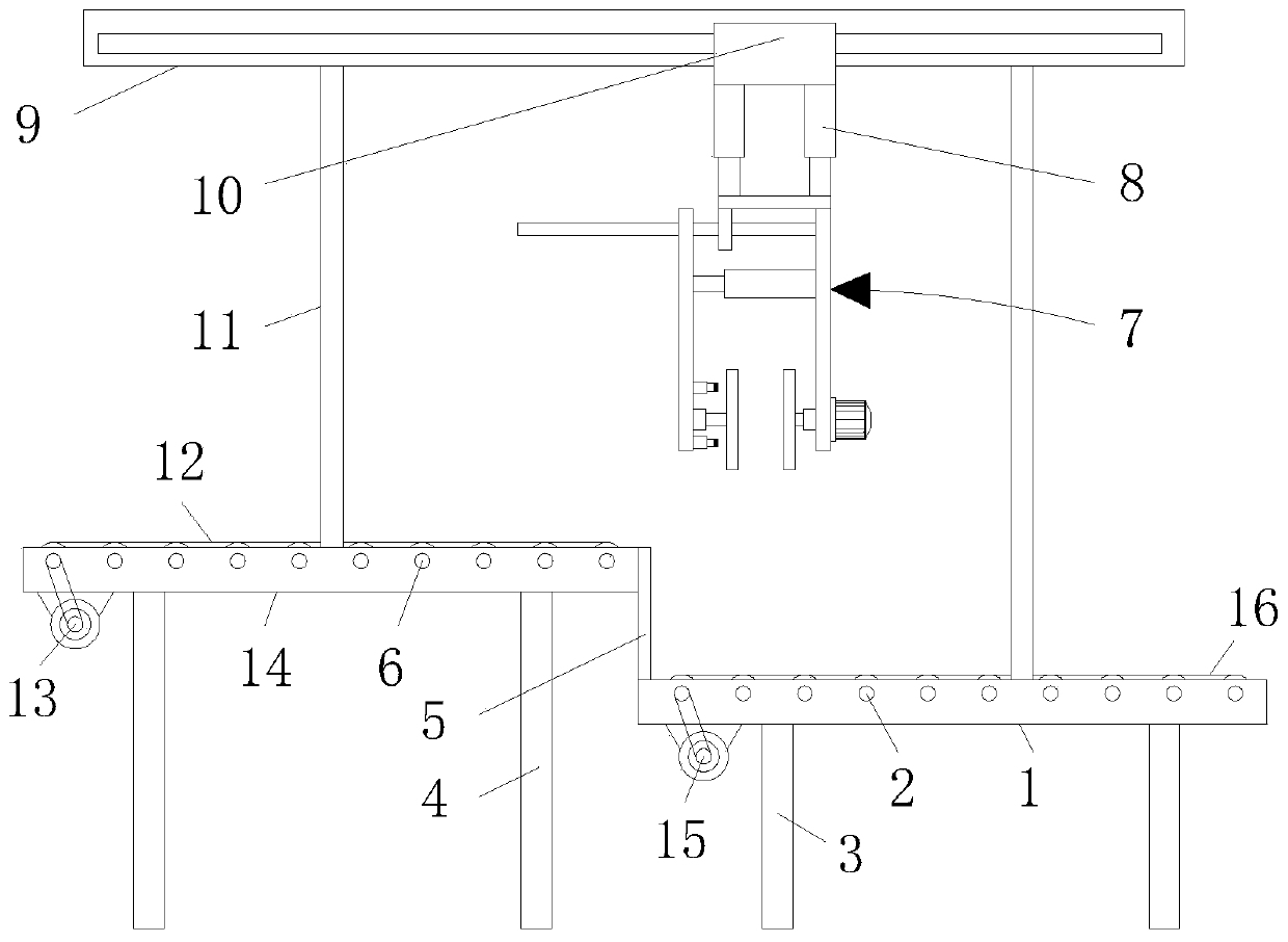
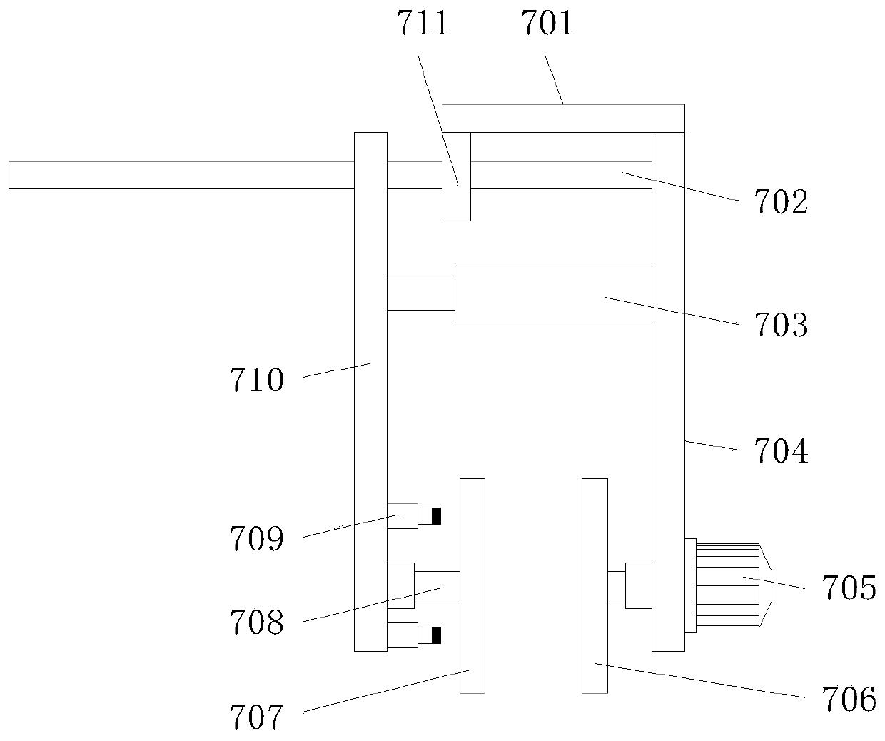
The invention discloses a clamping device for a battery of a new energy vehicle. The clamping device comprises a first support and a second support, a plurality of first conveying rollers which are distributed at equal distances and are in transmission connection through a first conveying belt are movably mounted on the inner surface of the first support, and a first motor is fixedly mounted at the front left end of the bottom of the first support, wherein an output shaft of the first motor is in transmission connection with the first conveying roller located at the leftmost end of the inner surface of the first support through a belt. A sliding seat and a slider are arranged so that the purpose of driving a clamping mechanism to move left and right can be achieved, a first electric telescopic rod is arranged so that the purpose of driving the clamping mechanism to move up and down can be achieved, the clamping mechanism is arranged so that the purposes of clamping the battery througha first clamping plate and a second clamping plate and steering the clamped battery can be achieved, through cooperation of the structures, the clamping efficiency of the clamping device for batteriesof different types is effectively improved, and great convenience is brought to use by people.

Description

technical field [0001] The invention relates to the technical field of new energy, in particular to a clamping device for a battery of a new energy vehicle. Background technique [0002] New energy, also known as unconventional energy, refers to various forms of energy other than traditional energy, and refers to energy that has just begun to be developed and utilized or is being actively researched and yet to be promoted, such as solar energy, geothermal energy, wind energy, ocean energy, biomass energy and Nuclear fusion energy, etc. New energy vehicles are one of the new energy applications. New energy vehicles are composed of many parts, and batteries are one of them. During the processing of batteries, clamping devices are needed to improve their processing efficiency. However, the existing battery clamping device cannot clamp different types of batteries, which is not conducive to the clamping of the battery. Therefore, we propose a clamping device for new energy vehic...

Claims


Application Information

Patent Timeline
Patent Type & Authority Applications(China)
IPC IPC(8): B65G15/22B65G47/90H01M2/10H01M50/249
CPCB65G15/22B65G47/902H01M50/20Y02E60/10
Inventor 戴桂兰
Owner 上海航空发动机制造有限公司
Why Eureka
Eureka Blog
Learn More