
Spring type automatic cable winding and unwinding device

An automatic cable, retractable device technology, applied in the field of spring-type automatic cable retraction device, can solve the problems of increasing the labor intensity of operators, poor retraction effect, cable wear, etc., to eliminate electric shock safety hazards, automatic retraction Good effect, avoid the effect of touching the ground

Pending Publication Date: 2020-08-25
杨玉岗
View PDF0 Cites 0 Cited by
  • Summary
  • Abstract
  • Description
  • Claims
  • Application Information

AI Technical Summary

Problems solved by technology

During the frequent advance and retreat of these electromechanical equipment in the underground and tunnel working faces, the tail cables often move randomly by manual dragging, which not only increases the labor intensity of the operators, but also has many potential safety hazards. In the process of retracting and unwinding the cables, on the one hand, the cables will be worn out; on the other hand, electric shock accidents may occur because the cables are in the energized state. In addition, because the operators operate behind the moving equipment, it is easy to cause equipment injury accidents
The structure of the cable retracting device in the prior art is complicated, and the retracting effect is not good, so there is an urgent need for an automatic retracting cable device to solve the above problems

Method used


Image

  • Spring type automatic cable winding and unwinding device
  • Spring type automatic cable winding and unwinding device
  • Spring type automatic cable winding and unwinding device

Examples


Embodiment 1

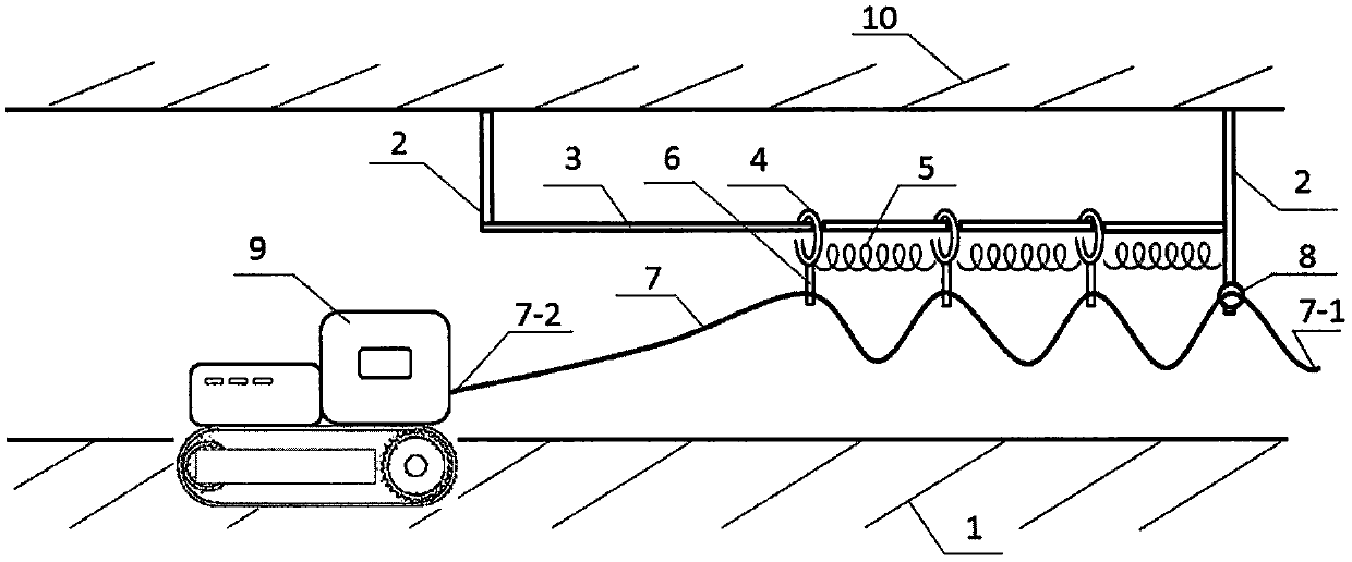
[0020] Refer to attached figure 1 with 2 , a spring-type automatic cable retracting device, including a bracket 2, a sliding rod 3, a slip ring 4, a spring 5, a cable clamp 6, a cable 7, a splint 8 and a mobile electromechanical device 9; it is characterized in that: two brackets 2 are respectively Fix it on the ground 1, install a sliding rod 3 between two brackets 2, set multiple slip rings 4 on the sliding rod 3, install a cable clamp 6 at the lower end of each slip ring 4, and connect one end 7-1 of the cable 7 to the AC For power supply, fix the splint 8 on the bracket 2 on the side adjacent to the cable terminal 7-1, fix the cable 7 with the splint 8, and install the springs 5 ​​sequentially between the bracket 2 on the side adjacent to the cable terminal 7-1 and each slip ring 4 , use the cable clamps 6 under the slip ring 4 to clamp the cables 7 respectively, and ensure that the cable length between two adjacent cable clamps 6 is not less than the length of each sprin...

Embodiment 2

[0024] Refer to attached image 3 , in order to save ground space, the bracket 2 in the first embodiment is fixed on the top of the mine or tunnel.

Embodiment 3

[0026] For the convenience of installation, the bracket 2 in the first embodiment is fixed on the wall of the tunnel, and the sliding rod 3 is replaced with a steel wire rope.


PUM


Abstract

The invention provides a spring type automatic cable winding and unwinding device. The spring type automatic cable winding and unwinding device comprises supports, a sliding rod, a plurality of sliding rings, springs, cable clamps, a cable, a clamping plate and a mobile electromechanical device. The sliding rod is mounted between the two supports. The sliding rod is sleeved with the plurality of sliding rings. The lower end of each sliding ring is provided with one cable clamp. One end of the cable is connected with an AC power supply. The clamping plate is fixed to the support adjacent to theAC power supply. The cable is fixed through the clamping plate. The springs are sequentially mounted between the clamping plate and the corresponding sliding ring and between the sliding rings. The cable is clamped through the cable clamps. The cable length between the two adjacent cable clamps is not less than the maximum stretched length of each spring. The other end of the cable is fixed to the tail of the mobile electromechanical device so as to supply power to a motor of the mobile electromechanical device. The spring type automatic cable winding and unwinding device has the beneficial effects that the spring type automatic cable winding and unwinding device is used for automatically winding and unwinding cables at the tails of various types of mobile electromechanical devices in mines and tunnels and has the advantages of being simple in structure, convenient to install, safe, reliable, low in cost, good in cable automatic winding and unwinding effect and the like.

Description

technical field [0001] This patent relates to a spring-type automatic cable retracting device applied to mobile electromechanical equipment in mines or tunnels. [0002] technical background [0003] Various mobile electromechanical equipment are often used in mines and tunnels, mainly including fully mechanized excavation equipment (rock roadheader, semi-coal rock roadheader, multifunctional roadheader), Roadway drilling equipment (hydraulic tunneling drilling rig, hydraulic side unloading rock loader, loader, hydraulic rock bolter for coal mine, drilling machine for coal mine), etc. During the frequent advance and retreat of these electromechanical equipment in the underground and tunnel working faces, the tail cables often move randomly by manual dragging, which not only increases the labor intensity of the operators, but also has many potential safety hazards. In the process of retracting and unwinding the cables, on the one hand, the cables will be worn out, and on the ...

Claims


Application Information

Patent Timeline
Patent Type & Authority Applications(China)
IPC IPC(8): B65H75/48B65H75/42
CPCB65H75/48B65H75/425B65H2701/34
Inventor 杨玉岗
Owner 杨玉岗
Learn More