Horizontal directional cohesionless soil sampling drilling tool used for unconsolidated fractured formation

A horizontally oriented, non-adhesive technology, applied in directional drilling, earth square drilling, sampling devices, etc., can solve the problems of inconvenient pulling out, inconvenient disassembly, and laborious, etc., to reduce disturbance, avoid falling off, and reduce soil sample drop The effect of falling chance

Inactive Publication Date: 2020-08-25
田欣浩
View PDF8 Cites 5 Cited by
  • Summary
  • Abstract
  • Description
  • Claims
  • Application Information

AI Technical Summary

Problems solved by technology

[0005] 1. In the prior art, the plugging part is closed under the action of the restoring force of the spring. At the same time, the sample descends slightly under the action of gravity, forming a negative pressure on the upper part to prevent the sample from falling off from the lower part. However, there is a certain amount of gas in the formation itself. It is difficult to negative pressure absorb the sample in the tube under the condition of shaking
[0006] 2. In the prior art, the outer wall of the drilling tool is relatively smooth, which can reduce the friction coefficient when inserted into the formation, but because the outer wall of the drilling tool is relatively smooth, it is inconvenient for workers to pull out the whole
[0007] 3. In the prior art, the drilling tool has an integrated structure, and it is inconvenient to disassemble. When checking the stratum structure after sampling, it is often necessary to push the soil sample out of the drilling tool, and this operation is laborious and cumbersome.

Method used


Image

  • Horizontal directional cohesionless soil sampling drilling tool used for unconsolidated fractured formation
  • Horizontal directional cohesionless soil sampling drilling tool used for unconsolidated fractured formation
  • Horizontal directional cohesionless soil sampling drilling tool used for unconsolidated fractured formation

Examples


Embodiment 1

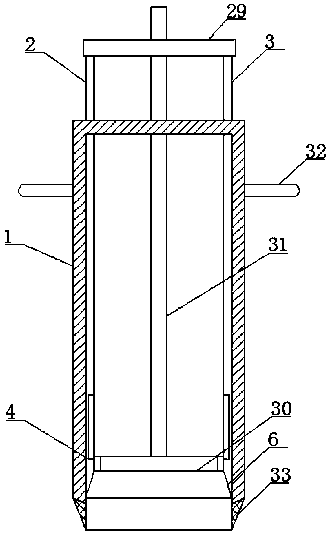
[0047] Such as Figure 1-8 As shown, the horizontally oriented non-cohesive soil sampling drilling tool for loose and broken formations according to the embodiment of the present invention includes a cylinder body 1 and a core pipe-2 and a core pipe arranged symmetrically in the cylinder body 1 Two 3, the core tube 1 2 and the core tube 2 3 are both semi-cylindrical structures, and the bottom ends of the core tube 2 and the core tube 2 3 are close to each other. A side slot 4 is provided, and a closing mechanism 5 is provided in the side slot 4. Through the setting of the closing mechanism 5, the arc-shaped baffle 18 is connected with the core tube 1 2 and the core tube 2 3 under the action of the block 23. The inner wall of the inner wall remains consistent and is on the same plane. After the coring is completed, press the backing plate 27 to move the block 23 downward and separate from the groove 21 of the arc-shaped baffle 18, and the arc-shaped baffle 18 is separated from ...

Embodiment 2

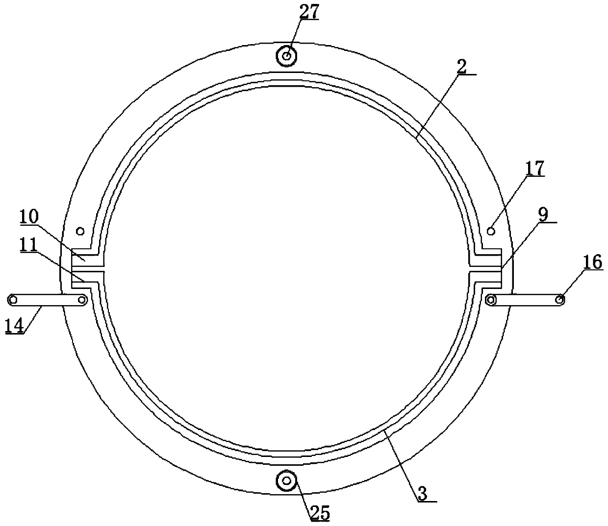
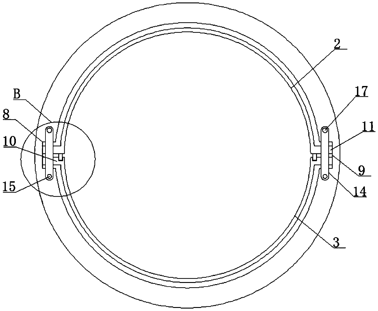
[0049] Such as Figure 1-3 As shown, on the basis of the first embodiment, the present invention provides a technical solution: the first limiting groove 8 and the second limiting groove 9 are arranged symmetrically on both sides of the cylinder body 1, and the first core tube 2 Both sides of the core tube two 3 are symmetrically provided with a fixed block one 10 and a fixed block two 11 matched with the limit slot one 8 and the two limit slot 9, and the core tube one 2 With the cooperation of the core tube two 3 and the limit groove one 8 and the limit groove two 9, the core tube one 2 and the core tube two 3 are combined to form a cylindrical structure, and the fixed block one 10 and the fixed block The second 11 is aligned with the limiting groove one 8 and the second limiting groove 9, and then inserted into the cylinder body 1, so that the core tube one 2 and the core tube two 3 are installed in the cylinder body 1, and after the sampling is completed, By pulling out th...

Embodiment 3

[0052] Such as Figure 1-3 As shown, on the basis of Embodiment 1 and Embodiment 2, the present invention provides a technical solution: the side of the core tube one 2 close to the core tube two 3 is provided with a bump 12, the One side of the core tube two 3 is provided with a fixed groove 13 matching the protrusion 12, and the top end of the core tube one 2 is located on one side of the limit groove one 8 and the limit groove two 9 All are provided with movable bar 14, and described movable bar 14 is connected with described coring tube one 2 by fixed shaft 15, and the other side of described movable bar 14 extends to the top of described coring tube two 3 and is provided with fixing. Hole 16, described fixing hole 16 is provided with the fixing bolt 17 that is connected with described coring tube two 3, by the setting of movable bar 14, the bottom of movable bar 14 is blocked stop-stop groove one 8 and stop-stop groove two 9. Make the fixed block 10 and the fixed block 2...


PUM


Abstract

The invention discloses a horizontal directional cohesionless soil sampling drilling tool used for an unconsolidated fractured formation. The drilling tool comprises a barrel, a first coring pipe anda second coring pipe, wherein the first coring pipe and the second coring pipe are arranged symmetrically in the barrel and are of semi-cylindrical structures correspondingly. Side grooves are formedin the bottom ends of the sides, close to each other, inside the first coring pipe and the second coring pipe correspondingly. Closing mechanisms are arranged in the side grooves correspondingly. By arranging the closing mechanisms, arc-shaped baffles are kept consistent with and located in the same planes with the inner walls of the first coring pipe and the second coring pipe correspondingly under the effects of corresponding clamping blocks, after sampling is completed, the effect of closing the bottoms of the first coring pipe and the second coring pipe is achieved by uplifting the barrelslightly and then pressing cushion plates, a sample is prevented from falling off from the lower portions, disturbance in a soil sample is reduced, the formation distribution situation can be observedintuitively by placing the first coring pipe and the second coring pipe horizontally on a work surface and taking away the coring pipes thereon, and the formation stratigraphic sequence status is kept in good condition.

Description

technical field [0001] The invention relates to the technical field of sampling drilling tools, in particular to a horizontally oriented non-cohesive soil sampling drilling tool for loose and broken formations. Background technique [0002] At present, mineral resources around the world are becoming increasingly depleted, which requires drilling companies to develop mineral resources more economically and effectively. To understand the structure and direction of mineral resources in the formation, in the existing technology, when sampling the soil, it is often Sampling drilling tools such as semi-combined pipes, multi-layer pipes, and piston drilling tools are used. [0003] Most of the existing domestic drilling and sampling methods for soft and shallow soil layers are vertical drilling, and there are very few horizontal drilling and sampling. However, in the process of vertical drilling and sampling, the distribution of soil samples in the horizontal direction cannot be a...

Claims


Application Information

Patent Timeline
IPC IPC(8): E21B25/16E21B7/04G01N1/08
CPCE21B25/16E21B7/046G01N1/08
Inventor 田欣浩
Owner 田欣浩
Why Eureka
Try Eureka