
Exhaust particle filter and vehicle

A particle trap and airflow technology, applied in the direction of exhaust devices, machines/engines, mechanical equipment, etc., can solve the problems of reducing engine torque output and fuel economy, increasing exhaust back pressure, and inconvenient use for users, etc., to achieve Prevent over-capture filtration, reduce the degree of filtration, and avoid the effect of rapid rise

Active Publication Date: 2022-01-14
CHINA FIRST AUTOMOBILE
View PDF8 Cites 0 Cited by
  • Summary
  • Abstract
  • Description
  • Claims
  • Application Information

AI Technical Summary

Problems solved by technology

As the mileage of the car increases, carbon particle deposition increases, and GPF regeneration measures need to be taken regularly to burn the attached carbon deposits. The combustion temperature generally must be above 550°C. The vehicle has to delay ignition, or even increase the speed, and the load increases. extremely inconvenient
The ash is a non-combustible particle, which cannot be eliminated by high temperature, and will permanently exist in the particle filter, blocking some of the wall filter holes
At present, the problems of the exhaust particulate filter are that the mileage of the accompanying vehicle increases, the filter holes are clogged, the exhaust back pressure increases, frequent regeneration is required, and the torque output of the engine and fuel economy are reduced.

Method used


Image

  • Exhaust particle filter and vehicle
  • Exhaust particle filter and vehicle
  • Exhaust particle filter and vehicle

Examples


Embodiment Construction

[0032] In order to make the technical problems solved by the present invention, the technical solutions adopted and the technical effects achieved clearer, the technical solutions of the embodiments of the present invention will be further described in detail below in conjunction with the accompanying drawings. Obviously, the described embodiments are only the technical solutions of the present invention. Some, but not all, embodiments. Based on the embodiments of the present invention, all other embodiments obtained by those skilled in the art without making creative efforts belong to the protection scope of the present invention.

[0033] In the description of the present invention, it should be noted that the terms "center", "upper", "lower", "left", "right", "vertical", "horizontal", "inner", "outer" etc. The indicated orientation or positional relationship is based on the orientation or positional relationship shown in the drawings, and is only for the convenience of desc...


PUM


Abstract

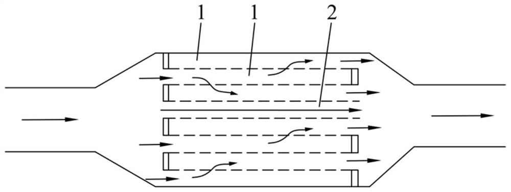
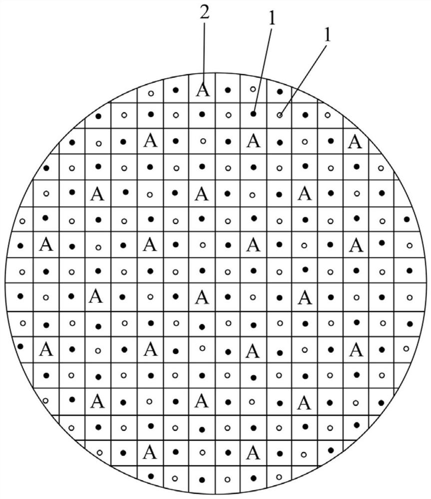
The invention discloses an exhaust particle trap and a vehicle, which belong to the field of motor vehicle exhaust. The exhaust particulate trap includes a filter channel, the filter channel includes a plurality of parallel adjacent flow channels, adjacent flow channels are separated by porous filter walls, the flow channels include a first flow channel and a second flow channel, the second flow channel One of the inlet and the outlet of the first flow channel is open, the inlet of the adjacent first flow channel is not opened at the same time, and the inlet and outlet of the second flow channel are both open. The vehicle includes the exhaust particulate trap described above. The second flow channel that connects both the inlet and the outlet is used as a fast flow channel for exhaust gas, and the degree of filtration of the exhaust gas flowing through the second flow channel is small, so that the degree of filtration of the overall exhaust gas is reduced and excessive particulate matter is prevented. Capture and filter, slow down the accumulation of carbon particles and ash on the porous filter wall, avoid the rapid rise of exhaust back pressure, reduce the regeneration frequency, and finally reduce the torque output loss of the engine.

Description

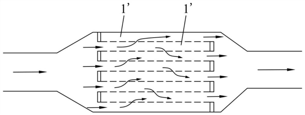
technical field [0001] The invention relates to the field of motor vehicle emission, in particular to an exhaust particle trap and a vehicle. Background technique [0002] With the stringent emission regulations, many gasoline engines need an exhaust particulate filter (Gasoline Particulate Filter, GPF) to capture carbon particles in the exhaust airflow to meet emission regulations. Such as figure 1 As shown, the existing exhaust particulate filter is a wall-flow type, including a plurality of parallel flow channels 1', and adjacent flow channels 1' are separated by porous and breathable thin-walled ceramics. When a flow channel 1' When the inlet is closed, the outlet is open, and the inlet of the adjacent flow channel 1' is open, and the outlet is closed. This structure leads to the fact that the exhaust must pass through the porous and air-permeable thin The wall ceramic enters the adjacent flow channel 1' with an open outlet and is discharged, and the particulate matter...

Claims


Application Information

Patent Timeline
Patent Type & Authority Patents(China)
IPC IPC(8): F01N3/022F01N3/035
CPCF01N3/022F01N3/035
Inventor 李金成黄平慧刘金玉刘道远王鹏安张强王占峰曲函师韩云峰马怀阳
Owner CHINA FIRST AUTOMOBILE
Learn More