Aerated grit chamber for sewage treatment

An aeration grit and sewage treatment technology, which is applied in the field of aeration grit chambers, can solve the problems of poor treatment effect, inability to crush and filter impurities, and poor aeration effect, so as to achieve improved filtration effect, convenient operation, and improved Effects of Processing Effects

Inactive Publication Date: 2021-02-09
高武
View PDF0 Cites 2 Cited by
  • Summary
  • Abstract
  • Description
  • Claims
  • Application Information

AI Technical Summary

Problems solved by technology

[0004] The object of the present invention is: in order to solve the shortcomings that the existing grit chambers cannot crush and filter the impurities in the sewage, the aeration effect is poor, and the treatment effect is not good, and a kind of aeration grit chamber for sewage treatment is proposed. sand pool

Method used


Image

  • Aerated grit chamber for sewage treatment
  • Aerated grit chamber for sewage treatment
  • Aerated grit chamber for sewage treatment

Examples


Embodiment 1

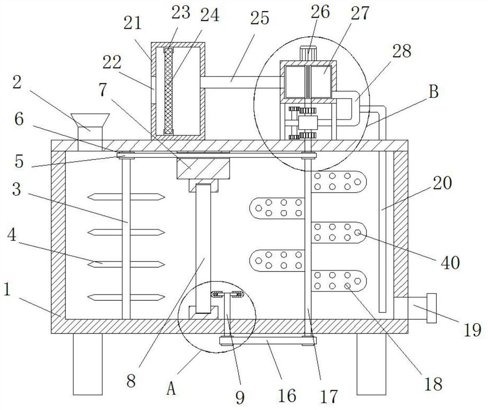
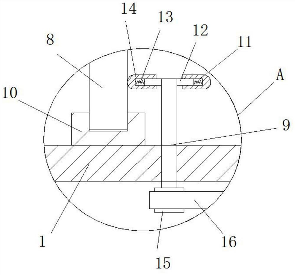
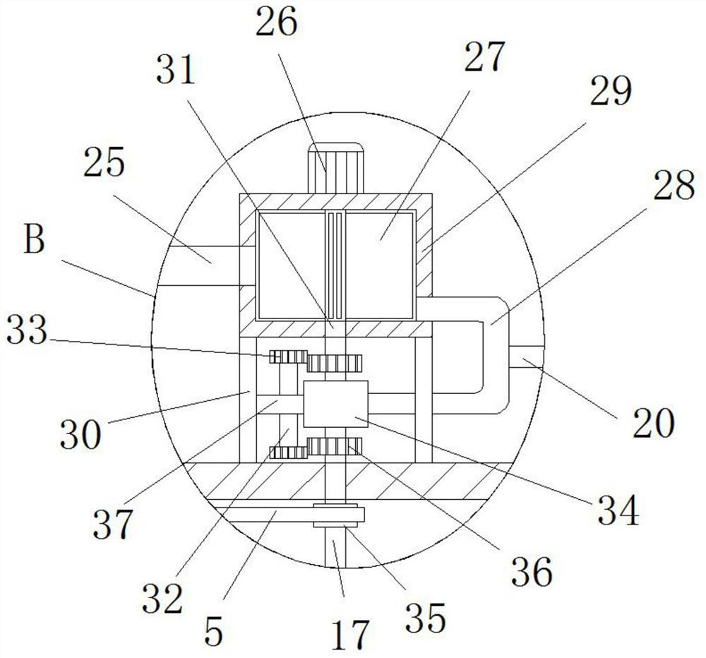
[0028] Please refer to Figure 1-Figure 5 , an aerated grit chamber for sewage treatment, comprising a treatment tank 1, the top of the treatment tank 1 is provided with a feeding port 2, one side of the treatment tank 1 is provided with a discharge pipe 19, and the vertical rotation in the treatment tank 1 is connected with Pulverizing shaft 3, a plurality of pulverizing knives 4 are fixedly installed on the outside of pulverizing shaft 3, fixed block 7 is fixedly installed on the top inner wall of treatment tank 1, all fixedly installed between the bottom of fixed block 7 and the bottom inner wall of treatment tank 1 Support bar 10, and support bar 10 is U-shaped structure, and the same filter screen 8 is movably connected between two support bars 10, and filter screen 8 can be disassembled, and the top of processing pool 1 is fixedly connected with rectangular box 21, and the rectangular box 21 The nutrient-rich film 24 is movably connected, and the top of the treatment poo...

Embodiment 2

[0039] Please refer to Figure 1-Figure 5 , an aerated grit chamber for sewage treatment, comprising a treatment tank 1, the top of the treatment tank 1 is provided with a feeding port 2, one side of the treatment tank 1 is provided with a discharge pipe 19, and the vertical rotation in the treatment tank 1 is connected with Pulverizing shaft 3, the outer side of pulverizing shaft 3 is fixedly installed with a plurality of pulverizing knives 4 by welding, on the top inner wall of processing tank 1, fixed block 7 is fixedly installed by welding, between the bottom of fixing block 7 and the bottom inner wall of processing tank 1 Both support bars 10 are fixedly installed by welding, and the support bars 10 are U-shaped structures. The same filter screen 8 is movably connected between the two support bars 10, and the filter screen 8 can be disassembled. The top of the treatment pool 1 is fixedly connected with a Rectangular box 21, nutrient-rich film 24 is movably connected in th...


PUM


Abstract

The invention discloses an aerated grit chamber for sewage treatment, which mainly comprises a treatment tank, a feeding port is formed in the top of the treatment tank, a discharging pipe is arrangedon one side of the treatment tank, a smashing shaft is vertically and rotationally connected into the treatment tank, a plurality of smashing cutters are fixedly installed on the outer side of the smashing shaft, and a fixing block is fixedly installed on the inner wall of the top of the treatment tank. Support bars are fixedly mounted between the bottom of the fixing block and the inner wall ofthe bottom of the treatment tank, each support bar is of a U-shaped structure, a same filter screen is movably connected between each pair of support bars, and a rectangular box is fixedly connected to the top of the treatment tank. A plurality of crushing shafts are arranged to drive the plurality of smashing cutters to crush residues in sewage, the sewage is filtered through the filter screens,and the filtering degree of the sewage can be improved by crushing the residues in the sewage; the aerated grit chamber is convenient to operate, impurities in sewage in the treatment tank can be crushed and filtered, the aeration effect is improved, and the treatment effect is improved.

Description

technical field [0001] The invention relates to the technical field of sewage treatment, in particular to an aeration grit chamber for sewage treatment. Background technique [0002] The aerated grit chamber is a long channel with a sand collecting bucket at its lower part. The bottom of the tank has a slope to ensure that the sand particles slide in. Due to the aeration, the organic particles in the wastewater are often in a suspended state, and the sand particles rub against each other and bear The shear force of aeration can remove the organic matter attached to the sand particles, which is beneficial to obtain relatively pure sand particles. Under the action of the centrifugal force of the swirling flow, these denser sand particles are thrown to the sand collection chamber, while the less dense organic matter It flows forward with the water flow and is taken to the next processing unit. [0003] The existing grit chamber cannot crush and filter the impurities in the sew...

Claims


Application Information

Patent Timeline
Patent Type & Authority Applications(China)
IPC IPC(8): C02F9/02B02C18/10B02C18/18B02C18/24
CPCB02C18/0092B02C18/10B02C18/18B02C18/24B02C2201/063C02F1/001C02F7/00C02F2001/007C02F2201/002
Inventor 高武
Owner 高武
Why Eureka
Try Eureka