Opening and closing sealing surface separation ball valve

A sealing surface and switch technology, which is applied to valve devices, cocks including cut-off devices, engine components, etc., can solve the problems of short service life, increased valve opening and closing torque, and large volume, so as to improve service life and reduce opening and closing. The effect of torque

Inactive Publication Date: 2020-08-25
FANGZHENG VALVE GRP
View PDF5 Cites 2 Cited by
  • Summary
  • Abstract
  • Description
  • Claims
  • Application Information

AI Technical Summary

Problems solved by technology

[0004] In the prior art, in order to meet the switching time requirements of valves, different automatic actuators can only be selected according to the different valve torques of different calibers and pressures; while the torque of large caliber and high pressure valves is often very large, it is necessary to configure a large Torque automatic actuators, and high-torque automatic actuators are often expensive and bulky; and cannot solve the problem of excessive wear on the sealing surface
In addition, when the valve is closed and the pipeline pressure increases, the pressure difference formed between the back of the valve seat and the sealing surface will drive the sealing ring of the valve seat to press against the ball to form a good seal. The sealing surface and the spherical surface are always in close contact. In the long run, the sealing surface is easily damaged, the service life is short, and the opening and closing torque of the valve is increased.

Method used


Image

  • Opening and closing sealing surface separation ball valve
  • Opening and closing sealing surface separation ball valve
  • Opening and closing sealing surface separation ball valve

Examples


Embodiment Construction

[0032] The present invention will be described in further detail below in conjunction with the accompanying drawings.

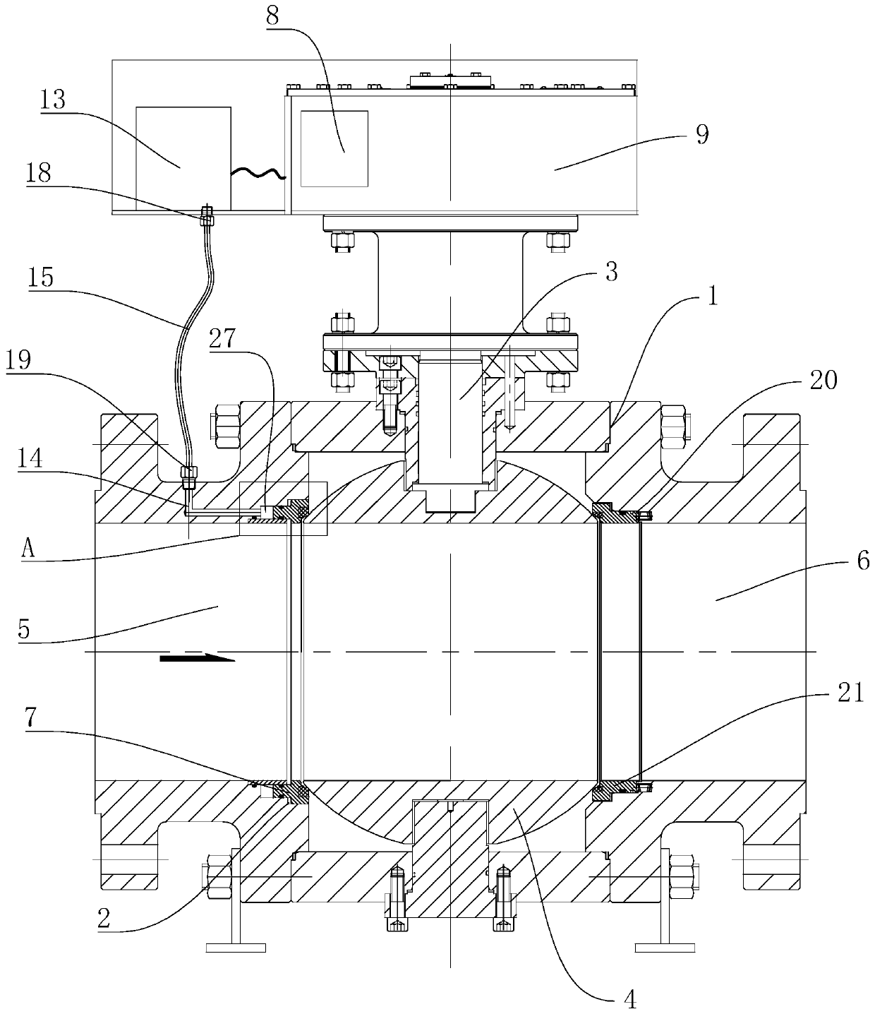
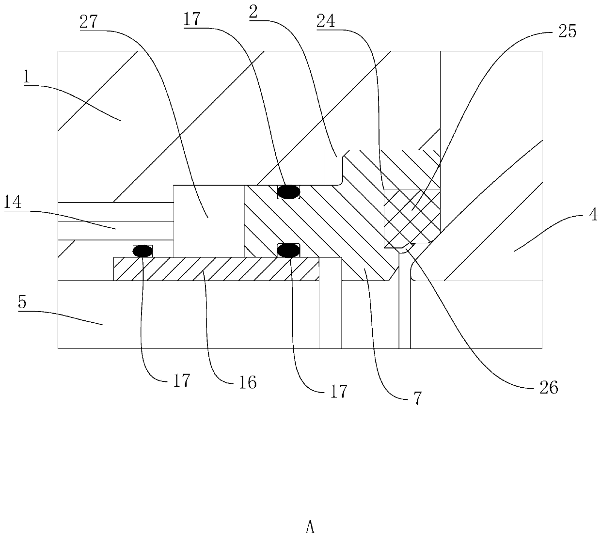
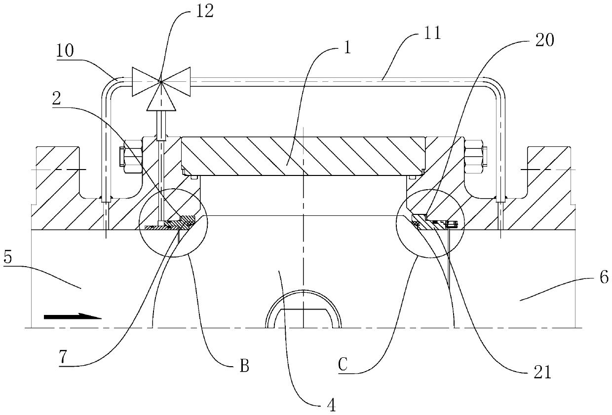
[0033] refer to Figure 1 to Figure 5 , a ball valve with a switch sealing surface detached, including a valve body 1 and a flow channel arranged in the valve body 1, an upstream installation groove 2 and a downstream installation groove 20, and the valve body 1 is equipped with a valve stem pierced into the interior of the valve body 1 3. One end of the valve stem 3 located inside the valve body 1 is equipped with an opening and closing member 4, and the opening and closing member 4 is a sphere. The opening and closing part 4 divides the flow channel into the inlet channel 5 and the outlet channel 6, the upstream installation groove 2 is located between the inlet channel 5 and the opening and closing part 4, and the downstream installation groove 20 is located between the outlet channel 6 and the opening and closing part 4 between. The upstream installatio...


PUM


Abstract

The invention discloses an opening and closing sealing surface separation ball valve. The ball valve comprises an automatic control and execution mechanism, a valve body, a flow channel and an upstream mounting groove; a valve rod is mounted on the valve body; an opening and closing piece is arranged on the valve rod and divides the flow channel into an inlet flow channel and an outlet flow channel; an upstream valve seat is glidingly arranged in the upstream mounting groove; the automatic control and execution mechanism comprises a controller and an actuator electrically connected with the controller; a closed driving cavity is formed between the upstream mounting groove and the upstream valve seat; the inlet flow channel communicates with the closed driving cavity through a first pipeline; the outlet flow channel communicates with a second pipeline; a switching piece for switching the medium flow direction is arranged between the first pipeline and the second pipeline; and a controlcomponent for controlling the pressure inside the closed driving cavity is arranged on the outer side of the valve body. The ball valve has the advantages and effects as follows: the upstream valve seat adopts the special valve seat adopting the detachable structure, the opening and closing torque of the valve can be reduced, the service life of the valve can be prolonged, and the better sealing effect can be achieved.

Description

technical field [0001] The invention relates to a valve, in particular to a ball valve with a switch sealing surface detached. Background technique [0002] Ball valve products are widely used in hydraulic system pipelines in various industries such as electric power, petrochemical, metallurgy, marine, petroleum, natural gas, gas, and pharmaceuticals. The torque of the existing trunnion ball valve is mainly composed of the friction torque between the ball and the sealing surface of the valve seat, the friction torque between the upper and lower valve stems and the bearing, etc., and the friction torque at these positions increases with the increase of the valve diameter and pressure level , especially high-pressure and large-diameter fixed ball valves, often need to be used in conjunction with automatic control actuators with very large torques, resulting in the cost of automatic control actuators being greater than the cost of the valve, and the total cost is greatly increa...

Claims


Application Information

Patent Timeline
Patent Type & Authority Applications(China)
IPC IPC(8): F16K5/20F16K5/06
CPCF16K5/0673F16K5/0689F16K5/205
Inventor 孙曾兴郝文明吴啸焦伦龄方品田
Owner FANGZHENG VALVE GRP
Why Eureka
Try Eureka