Gas return and sound eliminating master gas control valve for dental unit gas foot switch

A treatment machine, air valve technology, applied in dentistry, valve details, diaphragm valves, etc., can solve the problems of troublesome replacement, insufficient tightness, easy to leak air, etc., to achieve convenient disassembly and maintenance, fast and convenient installation, and convenient improvement. sexual effect

Pending Publication Date: 2020-08-25
LINKGOLD MEDICAL INSTR
0 Cites 0 Cited by

AI-Extracted Technical Summary

Problems solved by technology

[0003] The air return and noise reduction main control air valve of the air foot switch of the existing dental treatment machine, when not in use, the sealing performance between the three air cavities in the air valve is not tight enough, which...

Method used

In the present embodiment, the left and right sides of pedal 2 lower ends are all welded with the side spring 201 that bottom surface and air valve main body 1 u...

Abstract

The invention provides a gas return and sound eliminating master gas control valve for a dental unit gas foot switch and relates to the technical field of gas valves. The gas return and sound eliminating master gas control valve comprises a gas valve body, a pedal, a main gas cavity, a gas outlet cavity, a gas inlet cavity and a waste gas cavity. The main gas cavity is formed at the upper middle portion of the inner side of the gas valve body from top to bottom, the gas outlet cavity and the gas inlet cavity are formed in the centers of the left side and the right side of the gas valve body correspondingly and communicate with the main gas cavity, and the waste gas cavity is formed in the lower portion of the inner wall of the gas outlet cavity and communicates with the inner wall of the gas outlet cavity. The pedal comprises a main spring perpendicularly embedded in the inner side of the main gas cavity, a compression spring and a connecting rod integrated with the lower end of the main spring are welded to the lower end of the main spring through lasers, the connecting rod is located between the compression spring and the main spring, a soft pad is attached to the bottom of the compression spring, and the lower surface of the soft pad is attached to the bottom of the connecting position of the gas inlet cavity and the gas outlet cavity. The gas return and sound eliminating master gas control valve has the beneficial effects that the sealing performance of the gas valve is improved, and a silencer is conveniently replaced.

Application Domain

Diaphragm valvesEngine diaphragms +2

Technology Topic

PhysicsLaser soldering +6

Image

  • Gas return and sound eliminating master gas control valve for dental unit gas foot switch
  • Gas return and sound eliminating master gas control valve for dental unit gas foot switch
  • Gas return and sound eliminating master gas control valve for dental unit gas foot switch

Examples

  • Experimental program(1)

Example Embodiment

[0019] In order to make the objectives, technical solutions, and advantages of the present invention clearer, the following describes the present invention in detail with reference to the accompanying drawings and specific embodiments. It should be understood that the specific embodiments described herein are only used to explain the present invention, but not to limit the present invention.
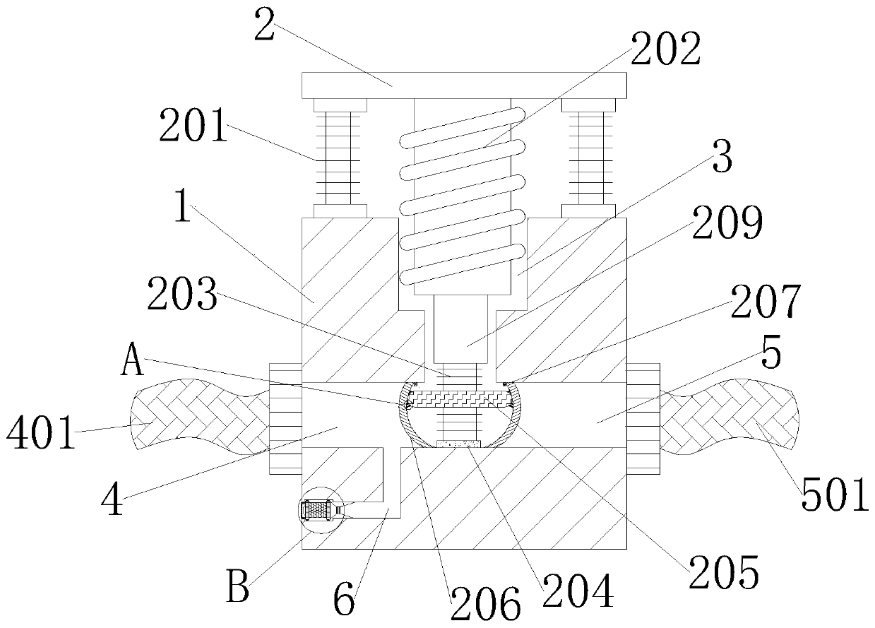
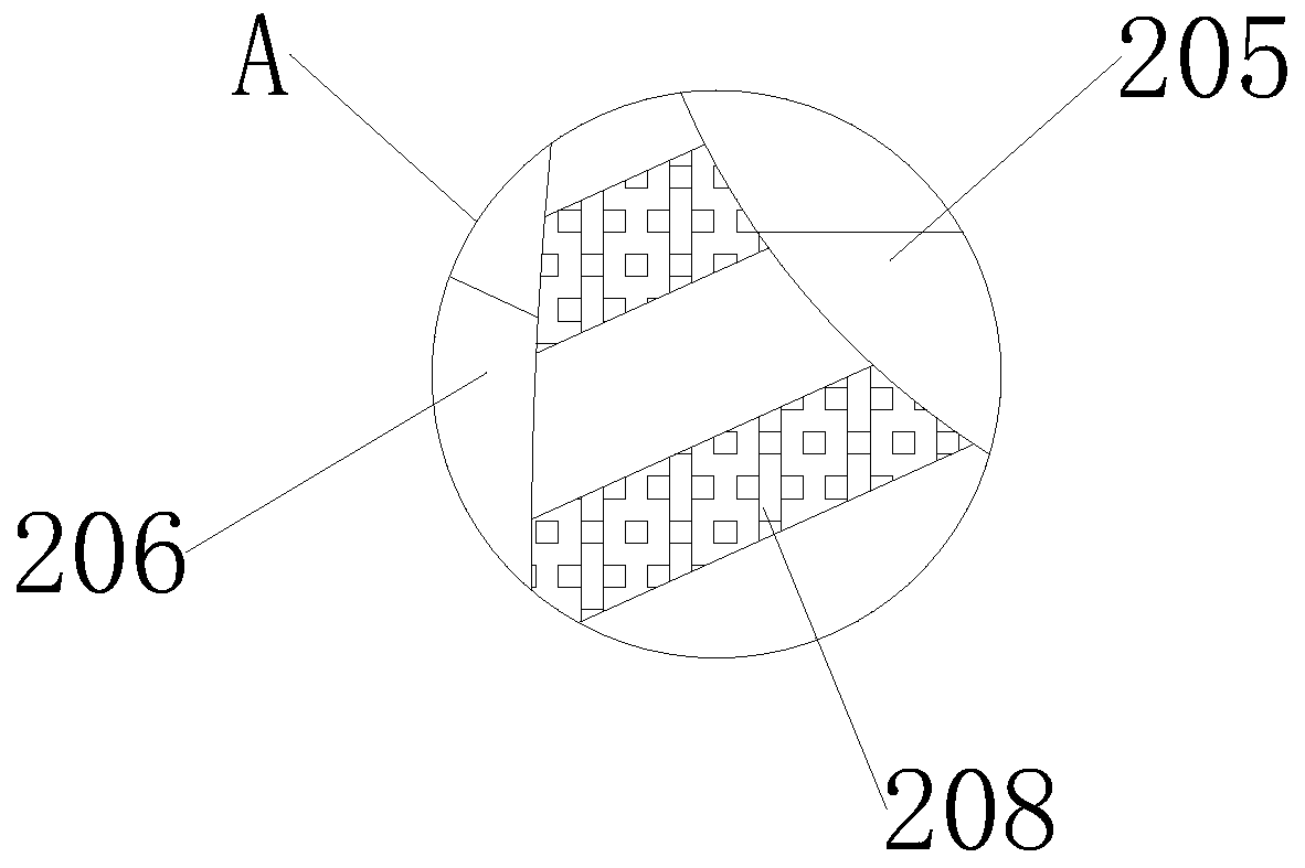
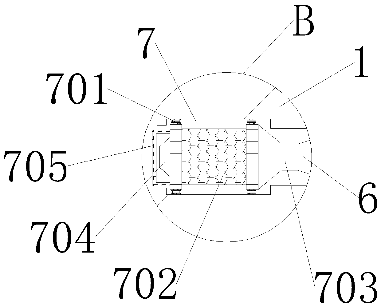
[0020] Such as Figure 1-3 As shown, a main control air valve for air return and noise reduction of an air foot switch of a dental treatment machine includes an air valve body 1, a pedal 2, a main air chamber 3, an air outlet chamber 4, an air inlet chamber 5, and a remaining air chamber 6. The air cavity 3 is opened from the top to the bottom in the upper middle of the inner side of the air valve body 1, and the outlet cavity 4 and the air inlet cavity 5 are respectively opened at the center of the left and right sides of the valve body 1 and communicate with the main air cavity 3. The remaining air cavity 6 It is opened below the inner wall of the air outlet chamber 4 and communicates with it. The pedal 2 is used to step on the user with his feet. The air outlet chamber 4 and the air inlet chamber 5 can achieve the function of air intake and air outlet, and the dental equipment can be discharged through the residual air chamber 6 Internal air
[0021] In the embodiment of the present invention, the pedal 2 includes a main spring 202 that is vertically embedded inside the main air cavity 3, and the lower end of the main spring 202 is laser welded with a compression spring 203 and a connecting rod 209 integrated therewith. The connecting rod 209 is located in the compression spring 203 and Between the main springs 202 and the bottom of the compression spring 203 is attached a soft cushion 204. The lower surface of the soft cushion 204 is attached to the bottom where the air inlet cavity 5 and the air outlet cavity 4 meet. The fixed horizontal plate 205, the left and right sides of the horizontal plate 205 are provided with rubber strips 208 and arc-shaped gaskets 206, and the rubber strips 208 are provided with at least three and are respectively bonded and fixed with the horizontal plate 205 by solvents, and the arc-shaped gaskets 206 Adhesively fixed by the adhesive strip 208 and the outer wall on the left and right sides of the horizontal plate 205, the two arc-shaped gaskets 206 are respectively vertically clamped at the junction of the air inlet cavity 5 and the air outlet cavity 4 with the main air cavity 3 and make the three It is in a sealed shape, and the upper inner walls of the air inlet cavity 5 and the air outlet cavity 4 are welded with two parallel blocks 207 above the inner wall of the two arc-shaped gaskets 206 respectively. The left end of the air outlet cavity 4 is inserted with an air outlet pipe 401 communicating with it. And the right end of the air intake chamber 5 is inserted with an air intake pipe 501 communicating with it, the end of the main spring 202 is embedded in the main air chamber 3, and the connecting rod 209 and the compression spring 203 are both embedded in the main air chamber 3, so that the compression spring The bottom surface of the soft pad 204 at the bottom of 203 is attached to the bottom where the inlet cavity 5 and the outlet cavity 4 meet. Then, the inlet cavity 5 and the outlet cavity 4 are sealed by two arc-shaped gaskets 206, so that the inlet The air chamber 5 and the air outlet chamber 4 are not connected to the main air chamber 3. The user connects the air outlet tube 401 of the air outlet chamber 4 with the pipeline of the dental equipment, and then steps on the pedal 2 with the foot and uses the main spring 202 The elastic nature makes the connecting rod 209 and the compression spring 203 press down, and the horizontal plate 205 fixed on the outer center of the compression spring 203 will press down with the compression spring 203, and will be bonded and fixed to the horizontal plate 205 by a rubber strip 208 The two arc-shaped gaskets 206 will slowly follow the horizontal plate 205 and fall down to the left and right sides, and slowly become horizontal. As a result, the air inlet cavity 5 and the air outlet cavity 4 are in communication with the main air cavity 3 , And the entire valve body 1 will also be in working condition. When the user releases the foot from the pedal 2, the compression spring 203 and the main spring 202 will slowly rebound upward, and the horizontal plate 205 will also drive The two arc-shaped gaskets 206 bounce up and make the arc-shaped gasket 206 in a vertical state, which prevents the outlet cavity 4 and the inlet cavity 5 from communicating with the main air cavity 3. The two stoppers 207 can be used to limit the position The role of the arc-shaped gasket 206 prevents air leakage when the arc-shaped gasket 206 bounces up beyond the outlet cavity 4 and the inlet cavity 5, which not only ensures the sealing performance of the valve body 1, but also effectively improves The working quality of the valve body 1;
[0022] In the embodiment of the present invention, there is a groove 7 on the lower left side of the inner side of the air valve body 1 and the end of the remaining air cavity 6, and the groove 7 includes an extrusion spring 701 and a silencer 702. The extrusion spring 701 is provided with four The muffler 702 is embedded in the groove 7 and clamped by four compression springs 701. The muffler 702 includes a connecting pipe 703, an exhaust pipe 704 and a hand The 705, the exhaust pipe 704 and the connecting pipe 703 are respectively inserted into the center positions of the left and right sides of the muffler 702 and communicate with the muffler 702. The mouth of the connecting pipe 703 is inserted into the end of the residual air cavity 6 and connected with it, and the handle 705 The upper and lower sides of the left end of the muffler 702 are welded by spot welding. The remaining air cavity 6 is parallel to the lower left side of the arc-shaped gasket 206 in the outlet cavity 4. The connecting pipe 703 is first inserted into the end of the remaining air cavity 6 to make the muffler 702 It communicates with the residual air cavity 6 through the connecting pipe 703, and the residual air generated in the dental equipment will enter the air outlet cavity 4 through the air outlet pipe 401. Because the user does not need to use the air valve body 1, the air inlet cavity 5 and the air outlet cavity 4 is not connected to the main air chamber 3, so the generated residual air will directly enter the muffler 702 through the residual air chamber 6, and be silenced by the muffler 702 and then discharged through the exhaust pipe 704, which can help reduce emissions. When the noise is generated during air and the muffler 702 fails, the user only needs to hold the handle 705 and push the muffler 702 up in the groove 7 so that the two compression springs 701 above the inner wall of the groove 7 After being compressed, the lower part of the muffler 702 can be detached from the inner wall of the groove 7, and the user can directly withdraw the muffler 702 from the groove 7 and replace it. This is not only convenient for disassembly and maintenance, but also quick and convenient for installation. , Which greatly improves the convenience of replacing the silencer 702.
[0023] In this embodiment, the lower and left sides of the pedal 2 are welded with side springs 201 fixed on the bottom surface and the upper surface of the valve body 1. The two side springs 201 can increase the rebound force of the pedal 2 and ensure The elasticity of the pedal 2.
[0024] The above descriptions are only preferred embodiments of the present invention and are not intended to limit the present invention. It should be pointed out that any modification, equivalent replacement and improvement made within the spirit and principle of the present invention shall include Within the protection scope of the present invention.

PUM

no PUM

Description & Claims & Application Information

We can also present the details of the Description, Claims and Application information to help users get a comprehensive understanding of the technical details of the patent, such as background art, summary of invention, brief description of drawings, description of embodiments, and other original content. On the other hand, users can also determine the specific scope of protection of the technology through the list of claims; as well as understand the changes in the life cycle of the technology with the presentation of the patent timeline. Login to view more.

Similar technology patents

Traffic sign detection method based on classification template matching

Owner:NO 8357 RES INST OF THE THIRD ACADEMY OF CHINA AEROSPACE SCI & IND

Classification and recommendation of technical efficacy words

  • Easy to disassemble and repair
  • reduce noise

Conical locking type strain clamp convenient for maintenance

Owner:LISHUI POWER SUPPLY COMPANY OF STATE GRID ZHEJIANG ELECTRIC POWER +2

Hand charger

InactiveCN103956817AEasy to disassemble and repair
Owner:刘骏涛

Press key structure

InactiveCN101770881AEasy to disassemble and repair
Owner:FOSHAN PREMIER SCI & TECH CO LTD +1

Extrusion soil breaker

Owner:ANHUI AGRICULTURAL UNIVERSITY

Liver subsection method based on CT image and system thereof

InactiveCN101425186Areduce noiseavoid blur
Owner:HUAZHONG UNIV OF SCI & TECH

Noise reduction device

ActiveUS20100014683A1reduce noisehigh quality
Owner:PANASONIC CORP

Automatic image capture

ActiveUS20110170740A1reduce noiseenhance edge
Owner:NORTHWEST IP LLC +1

Shift register electrode, grid electrode driver, array substrate and display device

InactiveCN102654986AReduced Threshold Voltage Driftreduce noise
Owner:BOE TECH GRP CO LTD +1
Why Eureka
Try Eureka