Easy-to-install hydraulic hose connector for engineering machinery

A technology of hydraulic pipe joints and construction machinery, which is applied in the direction of pipes/pipe joints/fittings, mechanical equipment, hose connection devices, etc., which can solve the problems of delay in construction period, inability to change the length, waste, etc., to save costs and improve piping efficiency , the effect of improving the utilization rate

Active Publication Date: 2020-08-25
浙江帕茨精工股份有限公司
View PDF14 Cites 2 Cited by
  • Summary
  • Abstract
  • Description
  • Claims
  • Application Information

AI Technical Summary

Problems solved by technology

[0002] At present, in the hydraulic system, hydraulic hoses are the most used when connecting the oil passages between various components, because the existing hydraulic hoses are made by crimping the buckle-type hose joints and the high-pressure hose connection ends. , The length of the high-pressure hose cannot be changed after the production is completed. In order to avoid the length of the hydraulic system pipeline, before the hydraulic system is connected to the pipeline, it is necessary to determine the length of the pipeline according to the distance between the components, and customize the hydraulic hose manufacturer according to the length. Hydraulic hoses will affect the assembly process of the hydraulic system during the piping process of the hydraulic system, delaying the construction period, and if there are errors in size measurement, the customized hydraulic hoses may not be used, which will cause waste; during the use of hydraulic hoses , the connection between the high-pressure hose and the buckle-type joint is prone to damage and leakage, so the entire hose can only be discarded as scrap, causing a lot of waste and bringing inconvenience to production and life

Method used


Image

  • Easy-to-install hydraulic hose connector for engineering machinery
  • Easy-to-install hydraulic hose connector for engineering machinery
  • Easy-to-install hydraulic hose connector for engineering machinery

Examples


Embodiment Construction

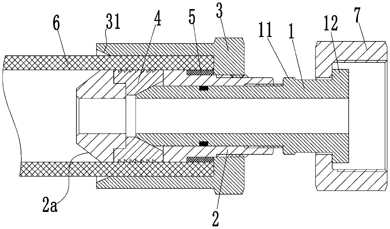
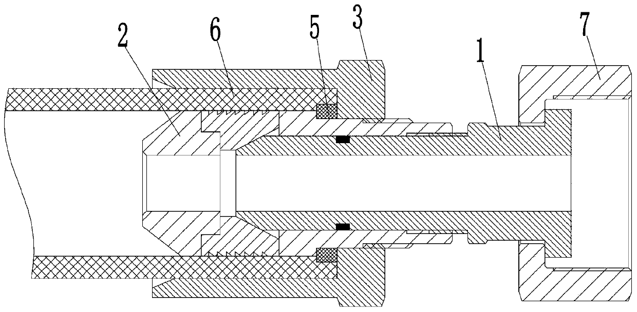
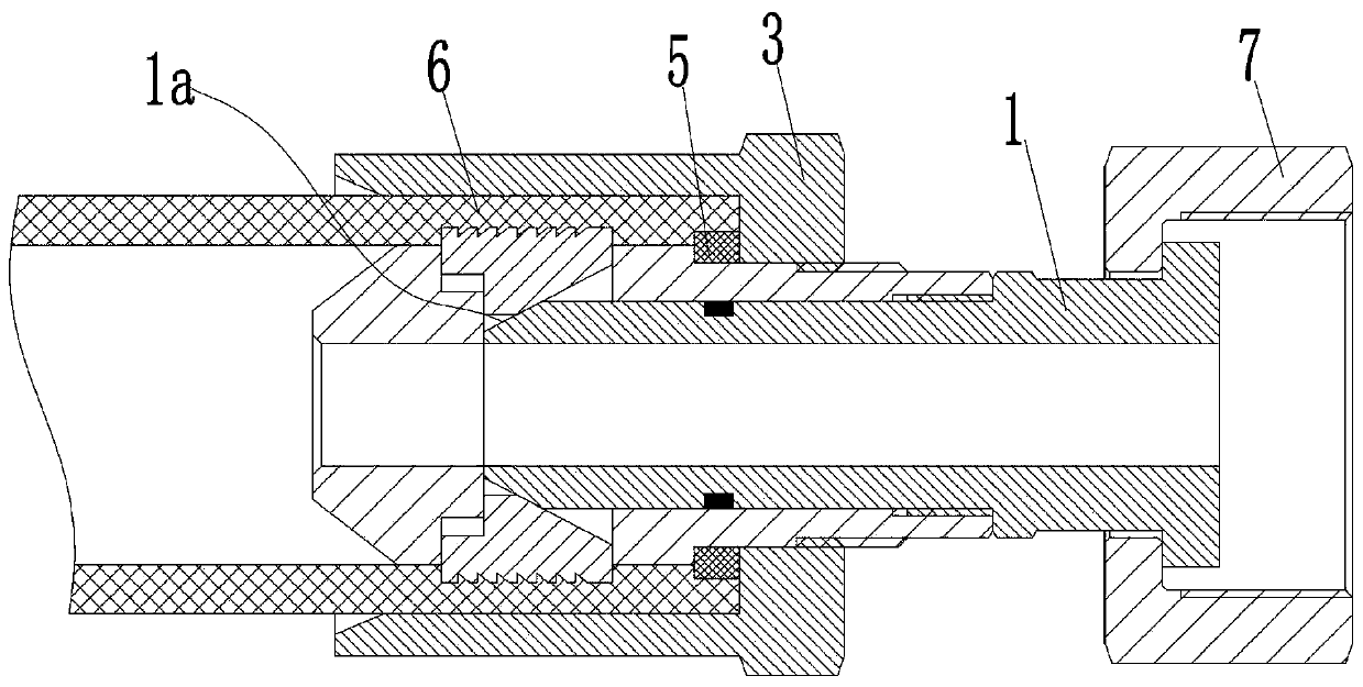
[0027] see Figure 1-4 As shown, an easy-to-install hydraulic pipe joint for engineering machinery includes an inner casing 2, and the inner casing 2 is threaded with a joint jacket 3 on the outer circumference side near the right end, and the joint jacket 3 and the inner casing 2 An annular intubation groove 201 is formed between them; the inner casing 2 is sleeved with a sealing ring 5 made of rubber material near the outer circumferential side of the joint jacket 3, and the joint jacket 3 is along the axis of the inner casing 2. When moving to the left, the extrusion sealing ring 5 protrudes outwards. The inner side wall of the inner sleeve 2 is provided with an annular cutout 21, and a plurality of notches 22 are evenly spaced along the circumferential direction on the side wall of the inner sleeve 2, and the notch 22 is connected with the intubation groove 201. It communicates with the annular groove 21, and the notch 22 is located at the left end of the annular groove 2...


PUM


Abstract

The invention discloses an easy-to-install hydraulic hose connector for engineering machinery. The connector comprises an inner sleeve, a connector outer sleeve is in threaded connection with the outer circumferential side face, close to the right end, of the inner sleeve, and an annular hose inserting groove is formed between the connector outer sleeve and the inner sleeve; an annular cutting groove is formed in the inner side wall of the inner sleeve, multiple notches are evenly formed in the side wall of the inner sleeve in the circumferential direction at intervals, the notches communicatewith the hose inserting groove and the annular cutting groove, and the notches are located in the left end of the annular cutting groove; a pressing block is slidably connected in each notch in the radial direction of the inner sleeve, a moving hose is in threaded connection with an opening in the right end of the annular cutting groove, and the left end of the moving hose extends into the annular cutting groove and is used for controlling the pressing blocks to extend into the hose inserting groove from the notches; and the right end of the moving hose is sleeved with a hose connector nut. The hydraulic rubber hose connector is simple in structure and capable of facilitating connection between a high-pressure hose and the connector.

Description

technical field [0001] The invention belongs to the technical field of hydraulic accessories, in particular to a hydraulic pipe joint. Background technique [0002] At present, in the hydraulic system, hydraulic hoses are the most used when connecting the oil passages between various components, because the existing hydraulic hoses are made by crimping the buckle-type hose joints and the high-pressure hose connection ends. , The length of the high-pressure hose cannot be changed after the production is completed. In order to avoid the length of the hydraulic system pipeline, before the hydraulic system is connected to the pipeline, it is necessary to determine the length of the pipeline according to the distance between the components, and customize the hydraulic hose manufacturer according to the length. Hydraulic hoses will affect the assembly process of the hydraulic system during the piping process of the hydraulic system, delaying the construction period, and if there a...

Claims


Application Information

Patent Timeline
Patent Type & Authority Applications(China)
IPC IPC(8): F16L33/22F16L33/18
CPCF16L33/003F16L33/18F16L33/224
Inventor 李奎张松霞
Owner 浙江帕茨精工股份有限公司
Why Eureka
Try Eureka