A detonator automatic production line automatic mold transfer equipment

An automatic production line and automatic technology, applied in the direction of detonators, offensive equipment, etc., can solve the problems of high manual labor intensity, large number of mold liners, hidden safety hazards, etc., and achieve the reduction of manual operation process, improve the efficiency of pipe arrangement, and improve efficiency Effect

Active Publication Date: 2021-06-15
YAHUA GROUP MIANYANG INDAL
View PDF0 Cites 0 Cited by
  • Summary
  • Abstract
  • Description
  • Claims
  • Application Information

AI Technical Summary

Problems solved by technology

[0002] In the prior art, in the automatic production line of electric detonators used by civil blasting equipment manufacturers, the basic detonators are usually manually or semi-automatically discharged from the combined mold of the turnover box and box. , can not effectively isolate man-machine, there is a large potential safety hazard, and the efficiency is low. This patented technology makes up for the shortcomings of the existing technology.

Method used


Image

  • A detonator automatic production line automatic mold transfer equipment
  • A detonator automatic production line automatic mold transfer equipment
  • A detonator automatic production line automatic mold transfer equipment

Examples


Embodiment 1

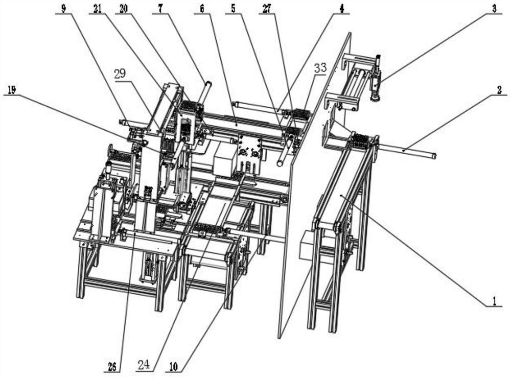
[0049] like figure 1 , figure 2 As shown, the present invention includes a first turnover box conveyor 1, a second turnover box conveyor 6, a two-dimensional platform 9, a support platform 31, a flattening mechanism 13, an upper box return box conversion mechanism 21 and a leaking pipe detection mechanism 14, The end of the first turnover box conveyor 1 is provided with a first box pushing cylinder 2 for pushing the turnover box 33 to the second turnover box conveyor 6, and above the end of the first turnover box conveyor 1 is provided with a box for pushing the turnover box 33 The box cover manipulator 3 that takes off the box cover, the second turnover box conveyor 6 end is provided with the second box pushing cylinder 7 that is used to push the turnover box 33 to the upper box return box conversion mechanism 21, and the upper box return box The conversion mechanism 21 is provided with a third box pushing cylinder 20 for pushing the turnover box 33 with the base pipe to th...

Embodiment 2

[0053] On the basis of the above examples, if figure 1 , figure 2 As shown, the upper box return conversion mechanism 21 is a double-layer structure with a lifting function.

[0054] The upper box returning conversion mechanism 21 is provided with a second box returning cylinder 19 for pushing empty turnover boxes 33 to the second turnover box conveyor 6 .

[0055] The top of the two-dimensional platform 9 is provided with a first box return cylinder 18 for pushing empty turnover boxes 33 to the upper box return conversion mechanism 21 .

[0056] The second turnover box conveyor 6 is provided with a third return box cylinder 5 and is adjacent to the first box push cylinder 2, and the third box return cylinder 5 is provided with an empty box limit cylinder 27 near the first box push cylinder 2 .

[0057] The second turnover box conveyor 6 is provided with a box returning platform 28 for over-empty turnover boxes 33 .

[0058] The box returning platform 28 is provided with ...

Embodiment 3

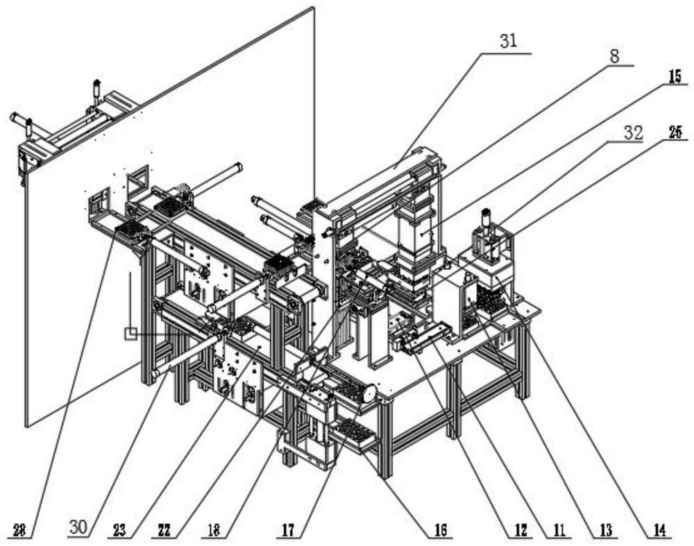
[0061] On the basis of the above examples, if Figure 1-2 As shown, the second turnover box conveyor 6 is provided with a combination mold conveyor 23 below, the combination mold conveyor 23 is provided with a fifth pushing mold cylinder 30, and the fifth pushing mold cylinder 30 is oppositely provided with a combination mold conveyor belt 24 , the combined mold conveyor belt 24 ends are provided with the first pushing mold cylinder 10, the combined mold conveyor 23 one end is provided with the dragging mold cylinder 17 and is close to the support platform 31, and the dragging mold cylinder 17 below is provided with the combination mold lifting upper mold mechanism 16.

[0062]Concrete, the mold dragging cylinder 17 is set above the upper mold mechanism 16 of the combination mold lifting, the combination mold 32 is lifted to the plane of the combination mold conveyor 23 through the combination mold lifting upper mold mechanism 16, and the mold pulling cylinder 17 drags the comb...


PUM


Abstract

The invention discloses an automatic mold transfer equipment for an automatic detonator production line. The first turnover box conveyor and the second turnover box conveyor transport the turnover box with the base tube to the upper box return box conversion mechanism, and push it to the second box through the box pushing cylinder. On the maintenance platform, the base pipe is ejected by the pipe jacking device, and the pipe grabbing manipulator grabs the base pipe and transports it to the lower pipe mechanism. Leaky pipes are pushed to the equipment of the next process after being qualified. The whole process realizes the automatic arrangement of substrate tubes, without excessive manual operation process, high efficiency, high safety, and high product qualification rate.

Description

technical field [0001] The invention relates to the technical field of civil explosives, in particular to an automatic mold-turning device for an automatic detonator production line. Background technique [0002] In the prior art, in the automatic production line of electric detonators used by civil blasting equipment manufacturers, the basic detonators are usually manually or semi-automatically discharged from the combined mold of the turnover box and box. , Human-machine isolation cannot be effectively carried out, there is a large potential safety hazard, and the efficiency is low. This patented technology makes up for the shortcomings of the existing technology. Contents of the invention [0003] The purpose of the present invention is to provide an automatic mold transfer equipment for an automatic detonator production line, which can improve the automation level of the automatic mold arrangement of the base tube, improve the efficiency, and improve the safety level, ...

Claims


Application Information

Patent Timeline
Patent Type & Authority Patents(China)
IPC IPC(8): C06C7/02
CPCC06C7/02
Inventor 袁春井唐杰邓超杨陈柯宇唐伟唐海王碟
Owner YAHUA GROUP MIANYANG INDAL
Why Eureka
Try Eureka