Oil slinger for warp knitting machine lubrication

A technology of oil slinger and warp knitting machine, applied in the field of oil slinger, can solve the problems of not being able to pick up more lubricating oil, low oil slinging efficiency, etc., and achieve the range of simple and quick installation process, high oil slinging efficiency, and splashing big effect

Active Publication Date: 2021-10-26
嘉兴万邦宏新材料科技有限公司
View PDF7 Cites 0 Cited by
  • Summary
  • Abstract
  • Description
  • Claims
  • Application Information

AI Technical Summary

Problems solved by technology

[0003] Publication No. CN203892850U is an oil throwing ring for lubricating warp knitting machines. The oil throwing ring is composed of two semi-circular bodies. One end of the two semi-circular bodies is hinged and the other end is connected by bolts. It can be used in daily assembly. It is convenient and quick to install and unload at any time, and does not conflict with other installation steps. However, the oil throwing ring can only be installed for a fixed-size shaft, and the oil throwing plate on the oil throwing ring is a flat plate. In the process of contact, the efficiency of oil rejection is low, and more lubricating oil cannot be picked up

Method used


Image

  • Oil slinger for warp knitting machine lubrication
  • Oil slinger for warp knitting machine lubrication
  • Oil slinger for warp knitting machine lubrication

Examples


Embodiment Construction

[0025] The following will clearly and completely describe the technical solutions in the embodiments of the present invention with reference to the accompanying drawings in the embodiments of the present invention. Obviously, the described embodiments are only some of the embodiments of the present invention, not all of them. Based on the embodiments of the present invention, all other embodiments obtained by persons of ordinary skill in the art without making creative efforts belong to the protection scope of the present invention.

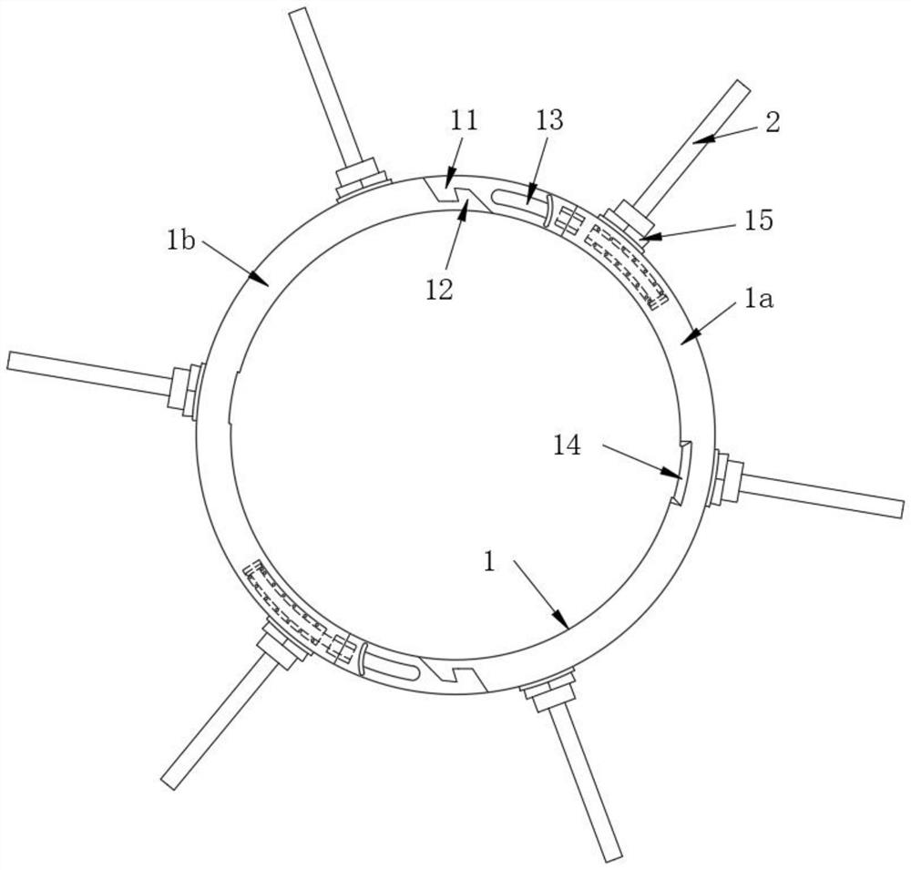
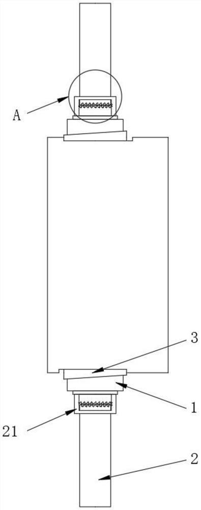
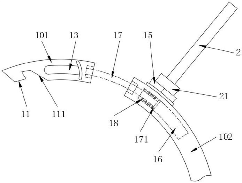
[0026] see Figure 1-5 , the present invention provides the following technical solutions: the oil throwing ring for warp knitting machine lubrication, comprising a ring body 1, the ring body 1 includes a first half-ring body 1a and a second half-ring body 1b engaged with each other, and the ring body 1 is at least composed of the first half-ring body 1a and the second half-ring body 1b An arc plate 101 and a second arc plate 102 are composed, th...


PUM


Abstract

The invention belongs to the technical field of oil throwing rings, in particular to an oil throwing ring for warp knitting machine lubrication, including a ring body, the ring body includes a first half ring body and a second half ring body engaged with each other, and the ring body is at least Composed of a first arc plate and a second arc plate, a hook is fixed at the end of the first arc plate far away from the second arc plate, and a hook is fixed at the end of the second arc plate far away from the first arc plate There is a hook seat; by setting two half-arc half-rings, the first arc plate and the second arc plate are elastically connected by a stretching shaft and a spring, and within the length of the stretching shaft, a relatively large diameter There is a diffusion plate on the shaft and the oil slinger outside the ring body. When the oil slinger extends below the oil liquid, more lubricating oil can be scooped out, so that when the oil slinger rotates, the More lubricating oil is brought out and splashed on the gears. The oil throwing plate can be inclined to both sides, so the splashing range is larger and the oil throwing efficiency is high.

Description

technical field [0001] The invention belongs to the technical field of oil throwing rings, and in particular relates to an oil throwing ring for lubricating a warp knitting machine. Background technique [0002] Use one or several groups of yarns arranged in parallel to form a knitted fabric at the same time on all the working needles of the warp feeding machine. This method is called warp knitting, and the fabric is called warp knitted fabric. The warp knitting machine is called a warp knitting machine. When the warp knitting machine is knitting, the lubricating oil inside the oil tank needs to be thrown up with an oil throwing ring to ensure that all parts inside the oil tank are fully lubricated. [0003] Publication No. CN203892850U is an oil throwing ring for lubricating warp knitting machines. The oil throwing ring is composed of two semi-circular bodies. One end of the two semi-circular bodies is hinged and the other end is connected by bolts. It can be used in daily ...

Claims


Application Information

Patent Timeline
Patent Type & Authority Patents(China)
IPC IPC(8): F16N7/22D04B35/28
CPCF16N7/22
Inventor 濮铁生
Owner 嘉兴万邦宏新材料科技有限公司
Why Eureka
Try Eureka