
Mapping method and device based on multi-line laser radar, medium and equipment

A multi-line laser and laser radar technology, which is applied in the direction of measuring devices, electromagnetic wave reradiation, radio wave measurement systems, etc., can solve problems that cannot be modeled as obstacles, and achieve the effect of improving accuracy

Active Publication Date: 2020-08-25
ZOOMLION ENVIRONMENTAL IND CO LTD
View PDF10 Cites 17 Cited by
  • Summary
  • Abstract
  • Description
  • Claims
  • Application Information

AI Technical Summary

Problems solved by technology

[0003] On the one hand, the present invention provides a mapping method based on multi-line laser radar to solve the technical problem that the low-height obstacles in the measurement blind area are too close to the mapping path and cannot be modeled as obstacles during the mapping process.

Method used


Image

  • Mapping method and device based on multi-line laser radar, medium and equipment
  • Mapping method and device based on multi-line laser radar, medium and equipment
  • Mapping method and device based on multi-line laser radar, medium and equipment

Examples


Embodiment Construction

[0047] It should be noted that, in the case of no conflict, the embodiments in the present application and the features in the embodiments can be combined with each other. The present invention will be described in detail below with reference to the accompanying drawings and examples.

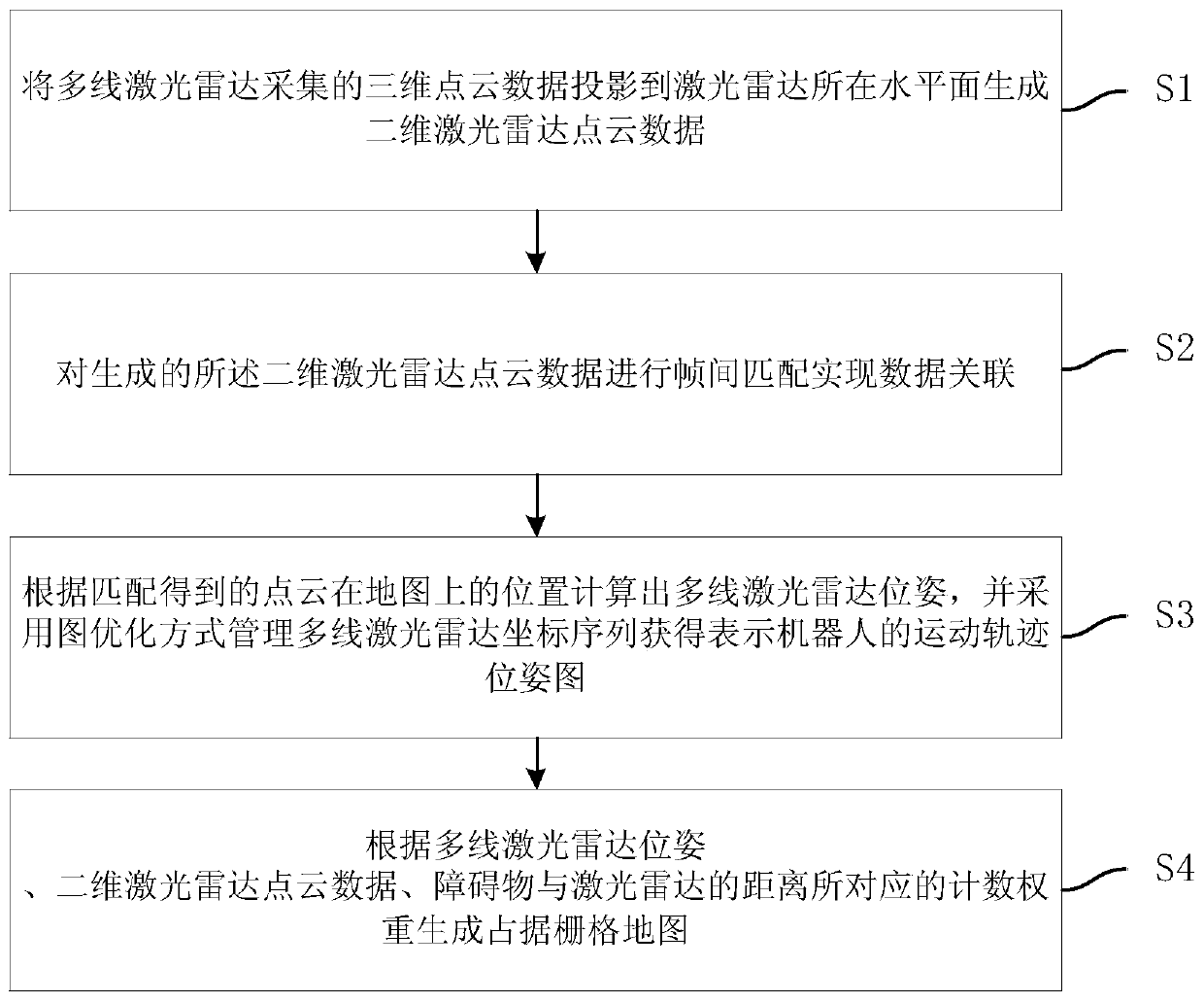
[0048] refer to figure 1 , the preferred embodiment of the present invention provides a kind of mapping method based on multi-line lidar, comprises steps:

[0049] S1. Project the three-dimensional point cloud data collected by the multi-line laser radar to the horizontal plane where the laser radar is located to generate two-dimensional laser radar point cloud data;

[0050] S2. Perform frame-to-frame matching on the generated two-dimensional lidar point cloud data to realize data association;

[0051] S3. Calculate the multi-line laser radar pose (position and orientation) according to the position of the matched point cloud on the map, and use graph optimization to manage the multi-line las...


PUM


Abstract

The invention discloses a mapping method and device based on a multi-line laser radar, a medium and equipment. The mapping method comprises the steps: projecting three-dimensional point cloud data collected by the multi-line laser radar to the horizontal plane where the laser radar is located to generate two-dimensional laser radar point cloud data; performing inter-frame matching on the generatedtwo-dimensional laser radar point cloud data to realize data association; calculating a multi-line laser radar pose according to the position of the point cloud obtained by matching on the map, and managing a multi-line laser radar coordinate sequence by adopting a graph optimization mode to obtain a motion trail pose graph representing the robot; and generating an occupied grid map according tothe multi-line laser radar pose, the two-dimensional laser radar point cloud data and the counting weight corresponding to the distance between the obstacle and the laser radar. According to the method, the problems that the low-height obstacle is close to the mapping path and a measurement blind area exists and cannot be modeled as an obstacle are solved, the modeling of the low-height obstacle in the map can be well processed, and the mapping accuracy and reliability are improved.

Description

technical field [0001] The present invention relates to the field of unmanned driving, in particular, to a mapping method, device, medium and equipment based on multi-line lidar. Background technique [0002] The environment map is the premise of positioning, navigation and path planning for robots. Simultaneous localization and mapping (SLAM) technology is an important means for mobile robots to obtain positioning and establish environmental maps. 2D laser SLAM is widely used by indoor robots because of its high precision and the ability to directly generate grid maps for navigation. However, 2D laser SLAM only has data on the plane where the single-line laser radar is located, and cannot handle other height obstacles. tall mobile robot. Although 3D lasers can generate 3D point cloud maps or other 3D maps of the scene, when such maps are used for navigation and motion planning of planar mobile robots, it is necessary to perform collision detection between the robot model a...

Claims


Application Information

Patent Timeline
Patent Type & Authority Applications(China)
IPC IPC(8): G01C21/00G01S17/08G01S17/89G01S7/48
CPCG01C21/005G01S17/08G01S17/89G01S7/4808
Inventor 陈凯张斌晋亚超张岁寒龚建球李亮罗新亮邵将
Owner ZOOMLION ENVIRONMENTAL IND CO LTD
Learn More