Rectifier diode module

A technology of rectifier diodes and rectifier circuits, which is applied in the direction of semiconductor/solid-state device components, semiconductor devices, electrical components, etc. Effect

Pending Publication Date: 2020-08-25
黄山市阊华电子有限责任公司
View PDF0 Cites 0 Cited by
  • Summary
  • Abstract
  • Description
  • Claims
  • Application Information

AI Technical Summary

Problems solved by technology

[0004] The purpose of the present invention is to provide a rectifier diode module, which solves the problem that the existing rectifier diode module is connected by a bridge, which has high stress, easy damage to the chip, and shortened service life.

Method used


Image

  • Rectifier diode module

Examples


Embodiment Construction

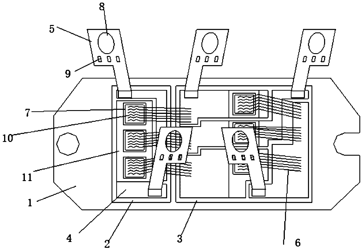
[0017] Examples such as figure 1 The shown rectifier diode module includes a base plate 1, two ceramic sheets 2 arranged on the base plate 1, two mounting holes 3 respectively arranged at the left and right ends of the base plate 1, and a group of copper clad areas 4 are arranged on the ceramic sheet 2 , the extraction electrode 5 arranged on the copper clad area 4 according to the rectification circuit is characterized in that: it also includes a set of chip dies 7 arranged on the ceramic sheet 2 according to the rectifier circuit and bonded to the chip die 7 and the copper clad area 4 between aluminum wire 6. The chip die 7 is soldered on the ceramic chip 2 with a green solder resist.

[0018] In describing the present invention, it is to be understood that the terms "central", "lateral", "upper", "lower", "left", "right", "vertical", "horizontal", "top", The orientation or positional relationship indicated by "bottom", "inner", "outer", etc. is based on the orientation or...


PUM

PropertyMeasurementUnit
diameteraaaaaaaaaa

Abstract

The invention relates to a rectifier diode module which comprises a bottom plate, two ceramic chips are arranged on the bottom plate, two mounting holes are respectively formed in the left end and theright end of the bottom plate, a group of copper-clad areas are set on the ceramic chips, and extraction electrodes are arranged on the copper-clad areas in a rectifying circuit mode, and the rectifier diode module also comprises a group of bare chips set on the ceramic chips according to a rectifying circuit and aluminum wires which are bonded between the bare chips and the copper-clad areas. The rectifier diode module can effectively solve the problems that an existing rectifier diode module is connected in a bridge connection mode, the stress is high, a chip is prone to damage, and the service life is shortened.

Description

technical field [0001] The invention relates to a rectifying diode module. Background technique [0002] In the prior art, the structure of the rectifier diode module basically includes a housing, components such as lead-out electrodes, copper connecting plates, bridges, diode chips, chip protection glue, ceramic copper-clad laminates, and copper bottom plates set in the housing. At the same time, lead-out electrodes, copper connecting plates, connecting bridges, diode chips, ceramic copper-clad laminates and copper base plate groups are packaged in the housing through epoxy resin. [0003] However, the connection through the bridge method has the problems of high stress, easy damage to the chip, and shortened service life. Contents of the invention [0004] The purpose of the present invention is to provide a rectifier diode module, which solves the problems that the existing rectifier diode modules are connected through a bridge, which has high stress, easily damaged ch...

Claims


Application Information

Patent Timeline
Patent Type & Authority Applications(China)
IPC IPC(8): H01L25/07H01L29/861H01L23/29H01L23/49
CPCH01L25/072H01L29/861H01L23/49H01L23/291H01L24/49H01L2224/4905H01L2224/4912H01L2224/495H01L2924/01013H01L2224/4846H01L2224/49111H01L2224/48227H01L2224/48472
Inventor 凌定华洪国东戴国中方新建
Owner 黄山市阊华电子有限责任公司
Why Eureka
Try Eureka