Motor and winding method thereof

A winding method and winding technology, which are applied in the manufacture of motor generators, electric components, electrical components, etc., can solve the problems of substandard motor performance and life, coil insulation wear and tear, and limited motor space, so as to increase the performance of the motor and motor life, simplify the production process, and improve the effect of commutation sparks

Pending Publication Date: 2020-08-25
SHANGHAI YILI ELECTRIC +1
View PDF0 Cites 2 Cited by
  • Summary
  • Abstract
  • Description
  • Claims
  • Application Information

AI Technical Summary

Problems solved by technology

[0002] At present, the number of commutator hooks and the number of rotor slots in general series motors are in integer multiples, such as a 12-hook commutator with a 12-slot rotor, or a 24-hook commutator with a 12-slot rotor, or a 36-hook commutator with a 12-slot rotor. 12-slot rotor; with such a traditional structural design, its winding process is simple and easy to implement
[0003] However, when the space of the motor is limited in this winding process, the space does not change or changes little, but the number of commutator hooks needs to be increased. It is easy to cause inter-turn short circuit (inter-turn short circuit is the failure of inter-turn short circuit caused by electromagnetic frequency multiplication vibration between the same-phase coils of the designated sub-end winding, which leads to coil insulation wear and tear), resulting in the performance and life of the motor not up to standard

Method used


Image

  • Motor and winding method thereof
  • Motor and winding method thereof
  • Motor and winding method thereof

Examples


Embodiment Construction

[0030] The specific implementation manners of the present invention will be further described in detail below in conjunction with the accompanying drawings and embodiments. The following examples are used to illustrate the present invention, but are not intended to limit the scope of the present invention.

[0031] The terms "first", "second", "third", "fourth" and the like in the description and claims of the present invention are used to distinguish similar objects, and are not necessarily used to describe a specific order or sequence .

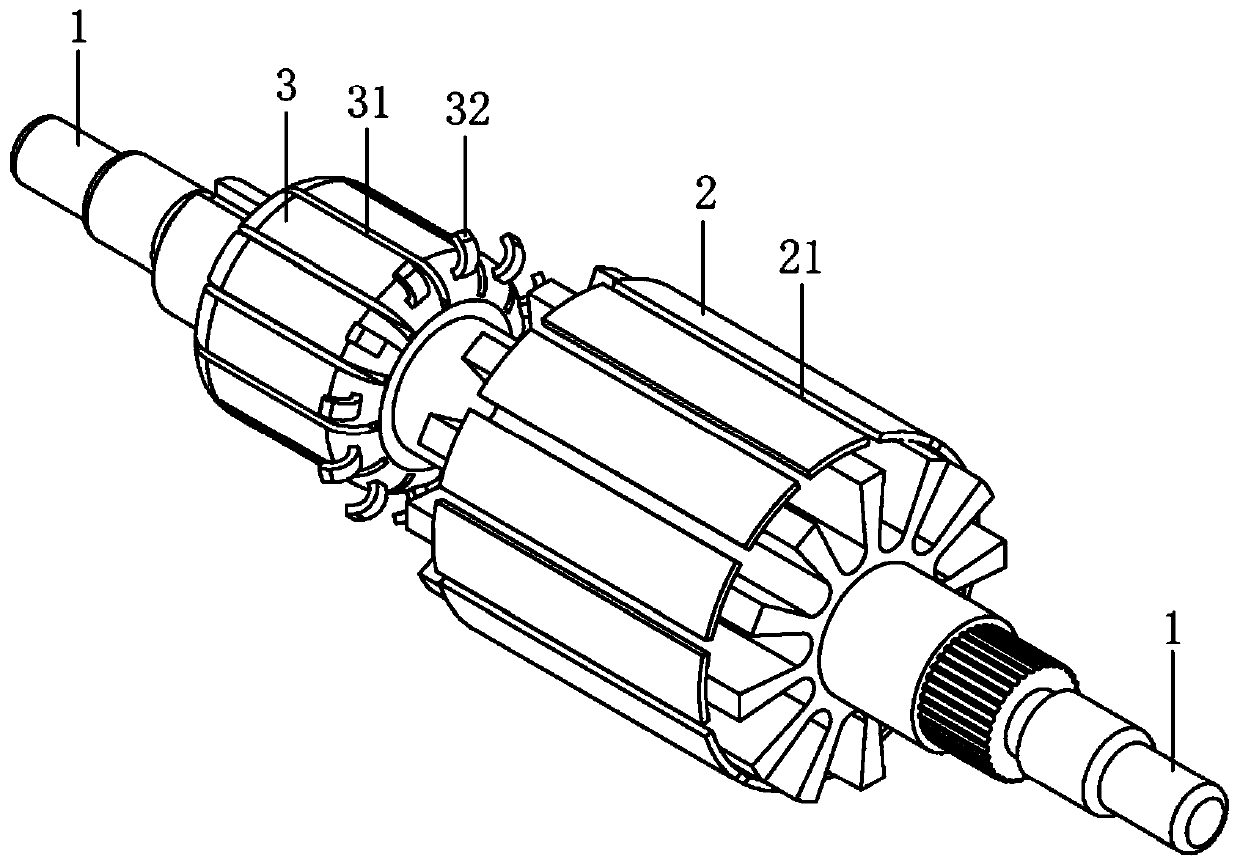
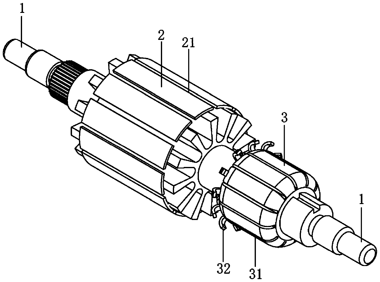
[0032] Please refer to the attached figure 1 , attached figure 2 , figure 1 It is a structural representation of the rotor shaft, rotor core and commutator of the motor provided by the present invention Figure 1 , figure 2 It is a structural representation of the rotor shaft, rotor core and commutator of the motor provided by the present invention Figure II .

[0033] Such as figure 1 and figure 2 As shown, the motor includes ...


PUM


Abstract

The invention relates to a motor and a winding method. A plurality of rotor core grooves are formed in a rotor core of the motor, a plurality of commutator grooves are formed in a commutator, a plurality of commutator hooks are arranged on the side, facing a rotor core, of the commutator, an enameled wire is wound in the commutator hooks and the rotor core grooves, and the number of the commutatorhooks is 1.5 times that of the rotor core grooves. The winding method comprises the following steps: 1, hanging a first commutator hook on an enameled wire, and winding a certain number of turns in afirst rotor iron core groove; 2, continuously hanging a second commutator hook on the enameled wire, and winding half of the turns in the first step in the first rotor iron core groove; 3, winding half of the turns of the enameled wire in the first step in a second rotor iron core groove; 4, hanging a third commutator hook on the enameled wire, and winding a certain number of turns in the secondrotor iron core groove; and taking the four steps as a cycle for winding until the last commutator hook is hung. The motor and the method have the advantages that turn-to-turn short circuit of the enameled wire is avoided; and meanwhile, reversing sparks of the motor are also improved.

Description

technical field [0001] The invention relates to the technical field of motors, in particular to a motor and a winding method thereof. Background technique [0002] At present, the number of commutator hooks and the number of rotor slots in general series motors are in integer multiples, such as a 12-hook commutator with a 12-slot rotor, or a 24-hook commutator with a 12-slot rotor, or a 36-hook commutator with a 12-slot rotor. 12-slot rotor; with such a traditional structural design, its winding process is simple and easy to implement. [0003] However, when the space of the motor is limited in this winding process, the space does not change or changes little, but the number of commutator hooks needs to be increased. It is easy to cause inter-turn short circuit (inter-turn short circuit is the failure of inter-turn short circuit caused by electromagnetic frequency multiplication vibration between the same-phase coils of the designated sub-end winding, which leads to coil in...

Claims


Application Information

Patent Timeline
Patent Type & Authority Applications(China)
IPC IPC(8): H02K23/00H02K1/26H02K15/09
CPCH02K1/265H02K15/09H02K23/00H02K2213/03
Inventor 单德刚王康瑞易三生武关振黄建平
Owner SHANGHAI YILI ELECTRIC
Why Eureka
Try Eureka