
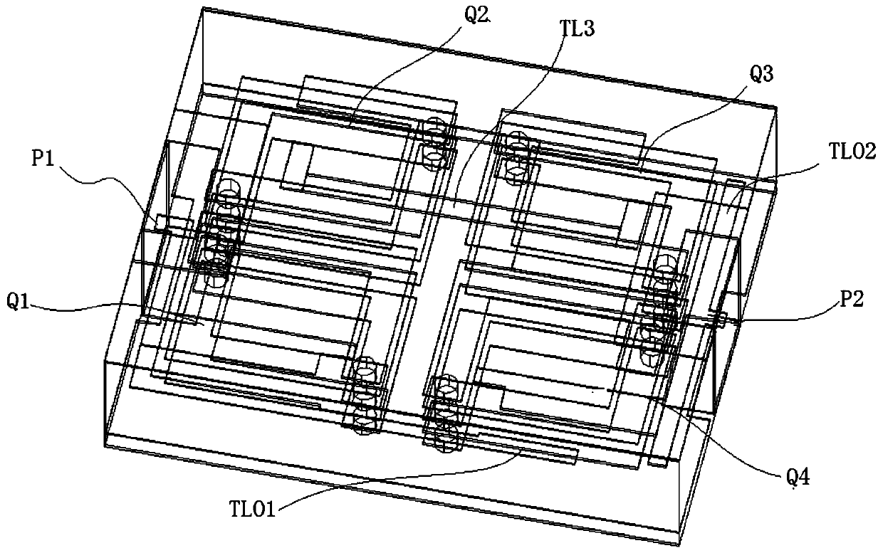
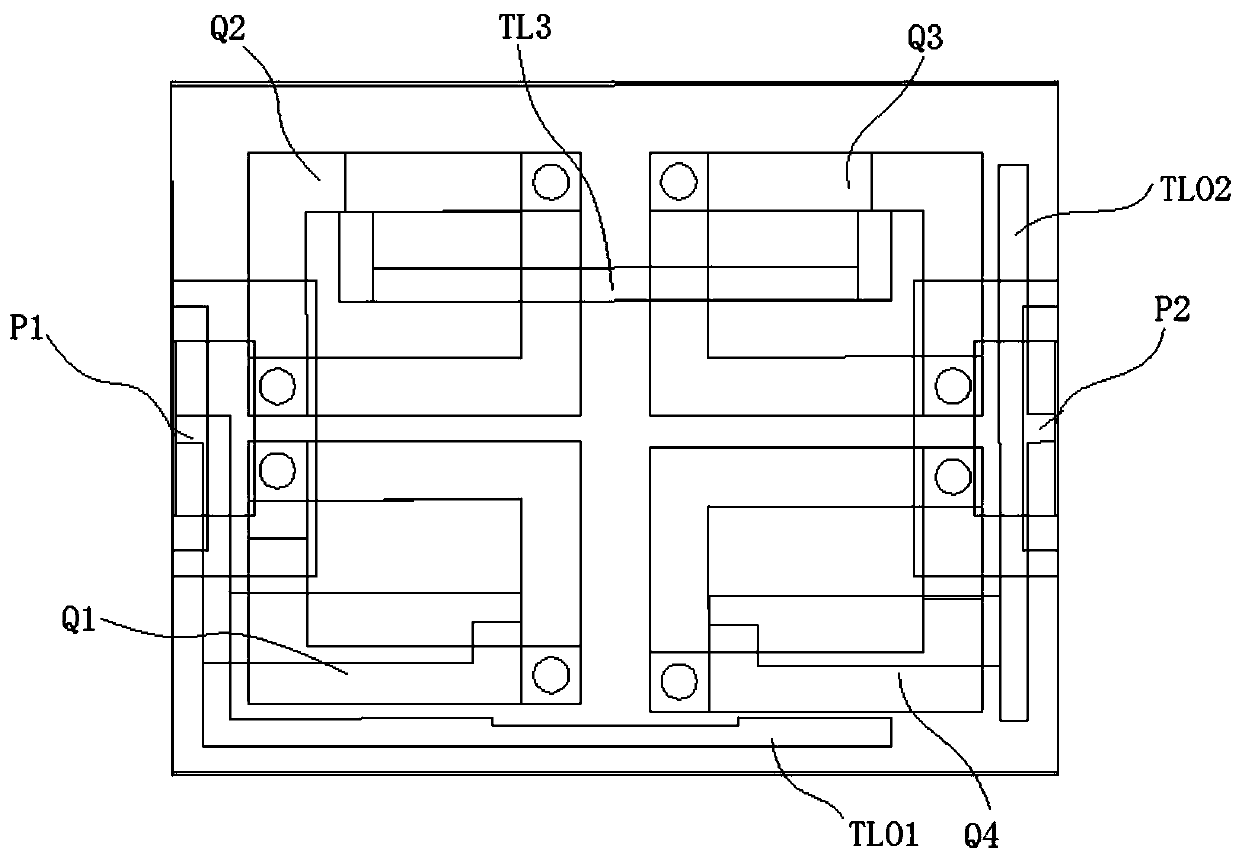
Multilayer filter

A filter and metal layer technology, applied in the filter field, can solve problems such as weak coupling, poor out-of-band rejection, and limited number of zeros

Pending Publication Date: 2020-08-25
WUHAN FINGU ELECTRONICS TECH
View PDF0 Cites 0 Cited by
  • Summary
  • Abstract
  • Description
  • Claims
  • Application Information

AI Technical Summary

Problems solved by technology

[0004] The embodiment of the present invention provides a multi-layer filter to solve the problems of limited number of zeros, poor out-of-band rejection and weak coupling in the prior art

Method used


Image

  • Multilayer filter
  • Multilayer filter
  • Multilayer filter

Examples


Embodiment Construction

[0023] In order to make the purpose, technical solutions and advantages of the embodiments of the present invention clearer, the technical solutions in the embodiments of the present invention will be clearly and completely described below in conjunction with the drawings in the embodiments of the present invention. Obviously, the described embodiments It is a part of embodiments of the present invention, but not all embodiments. Based on the embodiments of the present invention, all other embodiments obtained by persons of ordinary skill in the art without creative efforts fall within the protection scope of the present invention.

[0024] In describing the present invention, it should be understood that the terms "length", "width", "upper", "lower", "front", "rear", "left", "right", "vertical", The orientation or positional relationship indicated by "horizontal", "top", "bottom", "inner", "outer", etc. are based on the orientation or positional relationship shown in the draw...


PUM


Abstract

Disclosed is a multi-layer filter, open circuit branch knots are introduced N resonance units can generate more than N-2 zero points, and the out-of-band rejection is good; the position of the zero point can be flexibly controlled by adjusting the (electric) length of the open-circuit branch knot, the longer the line length is, the weaker the low-end capacitive zero point is (far away from the passband), and the stronger the high-end inductive zero point is (close to the passband), or vice versa. Through the connecting wires between the three-dimensional spiral inductors, on one hand, strongcoupling is realized, and on the other hand, the process realization difficulty is reduced, and the finished product yield is improved.

Description

technical field [0001] Embodiments of the present invention relate to the technical field of filters, in particular to a multi-layer filter. Background technique [0002] Nowadays, whether it is military radar, electronic detection, electronic countermeasures, etc., or civilian mobile phone communication, TV, and remote control, it is necessary to distribute and process electronic signals, which requires the use of an important microwave passive device-filter. [0003] With the rapid development of modern communication technology, small size, light weight, high performance, low cost, and wide bandwidth have become an inevitable trend in the development of modern communication systems. As the core frequency selection device in the transceiver system, the filter is used in the communication system to extract or filter out signals of different frequencies. The size of the traditional filter structure is large, and N resonant units can realize at most N-2 out-of-band transmissi...

Claims


Application Information

Patent Timeline
IPC IPC(8): H03H7/01
CPCH03H7/0115H03H7/0138H03H7/0153
Inventor 许建军
Owner WUHAN FINGU ELECTRONICS TECH
Learn More