Method and device in wireless communication

A wireless signal and signaling technology, applied in the field of CSI feedback, can solve the problem that the accuracy is difficult to meet the requirements of MU-MIMO transmission

Pending Publication Date: 2020-08-25
SHANGHAI LANGBO COMM TECH CO LTD
View PDF0 Cites 0 Cited by
  • Summary
  • Abstract
  • Description
  • Claims
  • Application Information

AI Technical Summary

Problems solved by technology

[0007] With the increase in the number of antennas equipped on the base station side, the accuracy of traditional implicit CSI is difficult to meet the requirements of MU-MIMO (multi-user multiple input multiple output) transmission

Method used


Image

  • Method and device in wireless communication
  • Method and device in wireless communication
  • Method and device in wireless communication

Examples


Embodiment 1

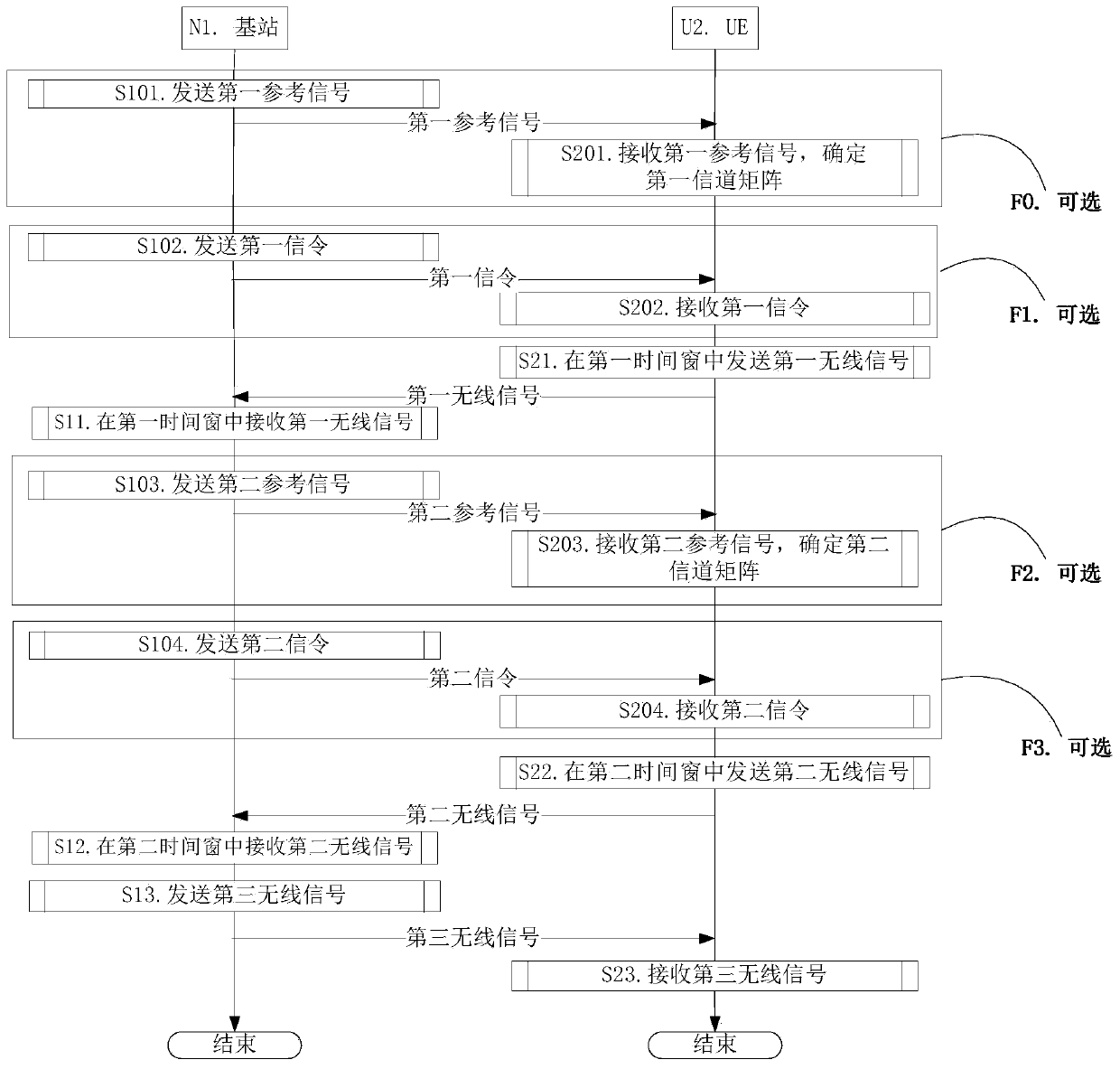
[0182] Embodiment 1 illustrates the flow chart of downlink transmission, as attached figure 1 shown. attached figure 1 In , the base station N1 is the serving cell maintenance base station of the UE U2. attached figure 1 , the steps in box F0, box F1, box F2 and box F3 are optional.

[0183] For N1, send the first reference signal in step S101; send the first signaling in step S102; receive the first wireless signal in step S11; send the second reference signal in step S103; send the second Signaling: receiving the second wireless signal in step S12; sending the third wireless signal in step S13.

[0184] For U2, receive the first reference signal in step S201, determine the first channel matrix; receive the first signaling in step S202; send the first wireless signal in the first time window in step S21; receive in step S203 The second reference signal is to determine a second channel matrix; receive second signaling in step S204; send a second wireless signal in a secon...

Embodiment 2

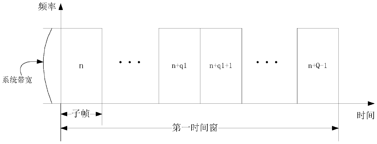
[0231] Embodiment 2 illustrates the schematic diagram of the first time window, as attached figure 2 shown.

[0232] In Embodiment 2, the first time window includes Q consecutive subframes, and the corresponding subframe indexes are {n, n+1, . . . , n+Q-1}.

[0233] The first parameter is sent in the first subframe in the first time window, that is, subframe n.

[0234] As a sub-embodiment 1 of Embodiment 2, the UE reports the first parameter only once in the first time window.

[0235] As a sub-embodiment 2 of Embodiment 2, the first information is sent in subframe n+q1 in the first time window.

Embodiment 3

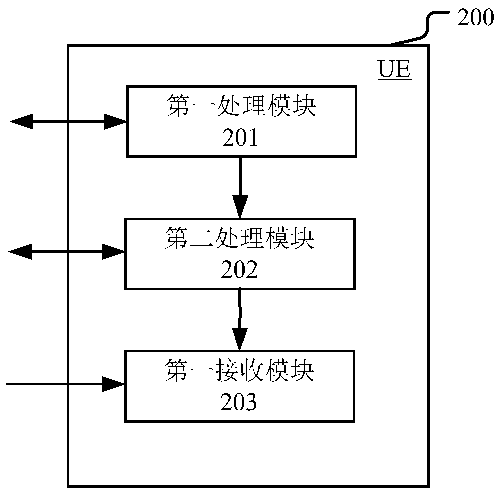
[0239] Embodiment 3 is a structural block diagram of a processing device used in UE, as shown in the attached image 3 shown. attached image 3 Among them, the UE device 200 is mainly composed of a first processing module 201 , a second processing module 202 and a first receiving module 203 .

[0240] The first processing module 201 is used to send the first wireless signal in the first time window; the second processing module 202 is used to send the second wireless signal in the second time window; the first receiving module 203 is used to receive the third wireless signal .

[0241] In Embodiment 3, the first wireless signal includes first information, and the second wireless signal includes second information. The first information and the second information are used to determine M merging vectors. The first information is used to determine M vector groups, and the second information is used to determine M coefficient groups. The M vector groups are in one-to-one corr...


PUM


Abstract

The invention provides a method and device in wireless communication. UE firstly sends a first wireless signal in a first time window and then sends a second wireless signal in a second time window, wherein the first wireless signal comprises first information, and the second wireless signal comprises second information. The first information and the second information are used to determine M merged vectors. The first information is used for determining M vector groups, and the second information is used for determining M coefficient groups. The M vector groups and the M coefficient groups arein one-to-one correspondence. The merged vector is generated by the vector groups and the corresponding coefficient groups. According to the invention, the CSI feedback overhead is reduced on the premise of ensuring the CSI feedback precision.

Description

[0001] This application is a divisional application of the following original application: [0002] --The filing date of the original application: 2016.06.22 [0003] --Application number of the original application: 201610454969.5 [0004] --The name of the invention of the original application: a method and device in wireless communication technical field [0005] The present invention relates to a method and device for multi-antenna transmission in the technical field of mobile communication, and in particular to a solution for CSI (Channel Status Information, channel state information) feedback in a scene where multiple antennas are deployed on a base station side. Background technique [0006] In downlink multi-antenna transmission, UE (User Equipment, user equipment) generally needs to feed back CSI to assist the base station in performing precoding. In a traditional 3rd Generation Partnership Project (3GPP-3rd Generation Partner Project) cellular network system, imp...

Claims


Application Information

Patent Timeline
Patent Type & Authority Applications(China)
IPC IPC(8): H04B7/0417H04B7/06
CPCH04B7/0421H04B7/0626H04B7/0636
Inventor 张晓博
Owner SHANGHAI LANGBO COMM TECH CO LTD
Why Eureka
Try Eureka