

Hydraulic fertilizer pushing mechanism with dual-layer baseplates
A hydraulic and bottom plate technology, applied in fertilization devices, fertilizer distributors, applications, etc., can solve problems such as poor stability and uniformity, achieve good stability and uniformity, and solve the effect of incomplete fertilizer delivery
- Summary
- Abstract
- Description
- Claims
- Application Information
AI Technical Summary
Problems solved by technology
Method used
Image

Examples
specific Embodiment approach 1
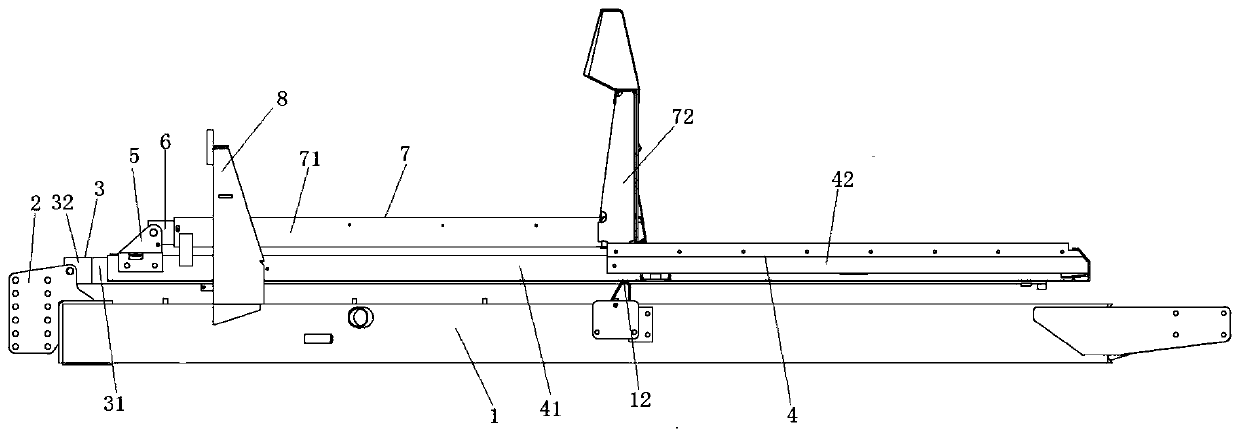
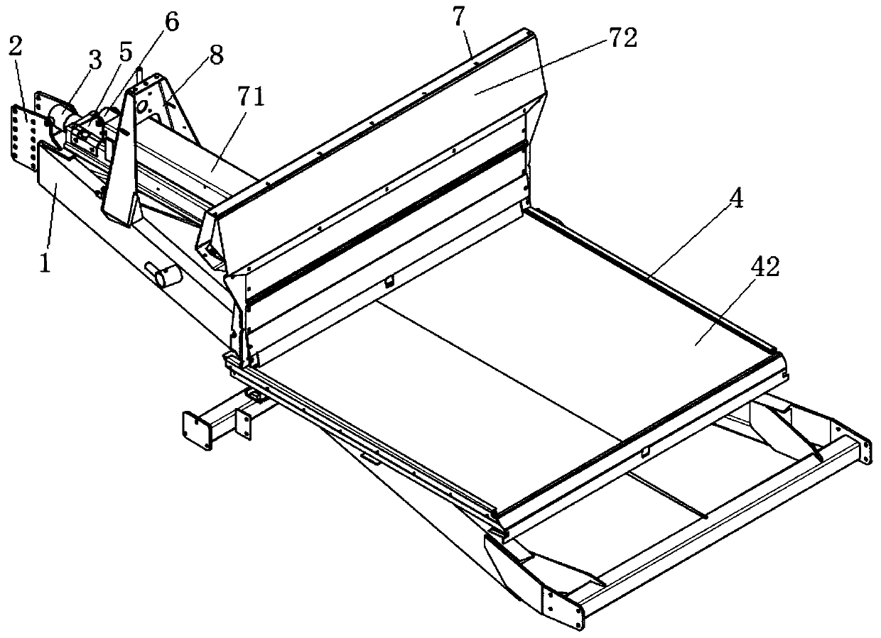
[0032] Specific implementation mode one: combine Figure 1-Figure 3 , Figure 7 Describe the present embodiment, a double-layer floor hydraulic fertilizer pushing mechanism of the present embodiment, including a traction frame base 1, a traction frame 2, a large hydraulic cylinder 3, a push-down fertilizer plate 4, a drive bracket 5, a small hydraulic cylinder 6 and Push up the fertilizer plate 7, the traction frame 2 is installed on the traction frame base 1, the cylinder part of the large hydraulic cylinder 3 is connected with the traction frame 2, the output end of the large hydraulic cylinder 3 is connected with the downward push fertilizer plate 4, and the downward push The fertilizer plate 4 is equipped with a drive bracket 5, the cylinder part of the small hydraulic cylinder 6 is connected with the drive bracket, the output end of the small hydraulic cylinder 6 is connected with the push-up fertilizer plate 7, and the upper end surface of the traction frame base 1 is co...
specific Embodiment approach 2
[0033] Specific implementation mode two: combination figure 1 , figure 2 , Figure 4 , Figure 6 and Figure 9 Describe this embodiment, a double-bottom hydraulic fertilizer pushing mechanism in this embodiment, the push-down fertilizer plate 4 includes a lower housing 41 and a lower push plate 42, and the large hydraulic cylinder 3 includes a first cylinder body 32 and a lower push plate 42. Lower piston rod 31, lower housing 41 covers the outer side of lower piston rod 31, the end of lower piston rod 31 is connected with lower push plate 42 by bolts, lower housing 41 is used to protect lower piston rod 31, to avoid lower piston rod 31 due to Long-term exposure shortens the service life of the piston rod 31;
[0034] Specifically, the first cylinder body 32 of the large hydraulic cylinder 3 is connected to the traction frame 2 in a hinged manner, so that the large hydraulic cylinder 3 can be more flexible, and the large hydraulic cylinder 3 can be adjusted according to t...
specific Embodiment approach 3
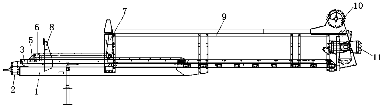
[0035] Specific implementation mode three: combination figure 1 , figure 2 , Figure 4 , Figure 5 and Figure 8 Describe this embodiment, a double-bottom hydraulic fertilizer pushing mechanism in this embodiment, the push-up fertilizer plate 7 includes an upper housing 71 and an upper push plate 72, and the small hydraulic cylinder 6 includes a second cylinder body 62 and Upper piston rod 61, upper housing 71 covers the outside of upper piston cover 61, the end of upper piston rod 61 is connected with upper push plate 72 by bolts, upper housing 71 is used to protect upper piston rod 61, to avoid upper piston rod 61 shortens the service life of the upper piston rod 61 due to long-term exposure;
[0036] Specifically, the second cylinder body 62 of the small hydraulic cylinder 6 is connected to the drive bracket 5 in a hinged manner, so that the small hydraulic cylinder 6 has better flexibility, and the angle of the small hydraulic cylinder 6 can be adjusted according to r...
PUM
 Abstract
Description
Claims
Application Information