Fracture fixation protective device

A fixed protection and guard plate technology, applied in fractures, non-surgical orthopaedic surgery, medical science, etc., can solve the problems of inconvenient rehabilitation, long fracture cycle, troublesome operation, etc., and achieve the effect of improving versatility, ingenious conception, and ingenious structure.

Inactive Publication Date: 2020-08-28
HENAN PROVINCE HOSPITAL OF TCM THE SECOND AFFILIATED HOSPITAL OF HENAN UNIV OF TCM
View PDF6 Cites 0 Cited by
  • Summary
  • Abstract
  • Description
  • Claims
  • Application Information

AI Technical Summary

Problems solved by technology

The traditional bandage fixation method is to use bandages and splints or plaster fixation. This method is cumbersome and requires professionals to implement, and there are great differences in the bandage strength of different personnel, which is likely to bring pain to the injured
However, although the internal fixation method with steel needles by traditional surgery is firm, but wearing steel needles increases secondary trauma, and requires a second operation to remove the steel needles after healing, and at the same time increases the risk of infection
[0003] Many existing finger fracture protection devices cannot be well adapted to different situations. For example, each person's multiple fingers have different thicknesses, and each patient's situation is also different. In terms of protection, many protection structures use the same In this way, some protections are too loose and easy to fall off, and some are too tight to cause extrusion, which is not easy to recover. In addition, fingers are used most in daily life, and the protection period of fractures is generally longer. The fully sealed treatment is not conducive to recovery, and the use of fully breathable water is easy to cause moisture in the daily washing and care actions, which is easy to be infected

Method used


Image

  • Fracture fixation protective device
  • Fracture fixation protective device
  • Fracture fixation protective device

Examples


Embodiment Construction

[0026] Embodiments of the technical solutions of the present invention will be described in detail below in conjunction with the accompanying drawings.

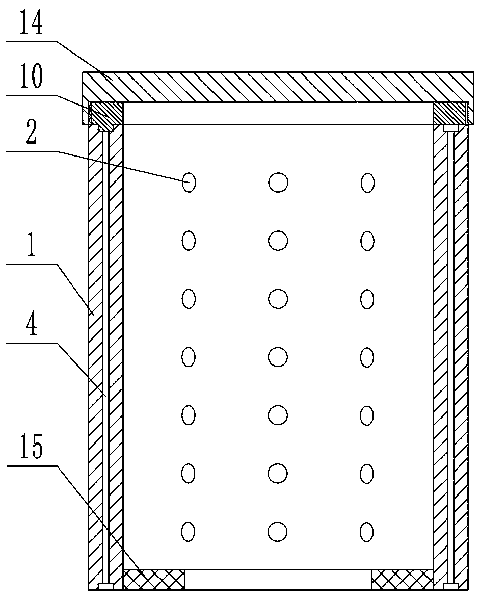
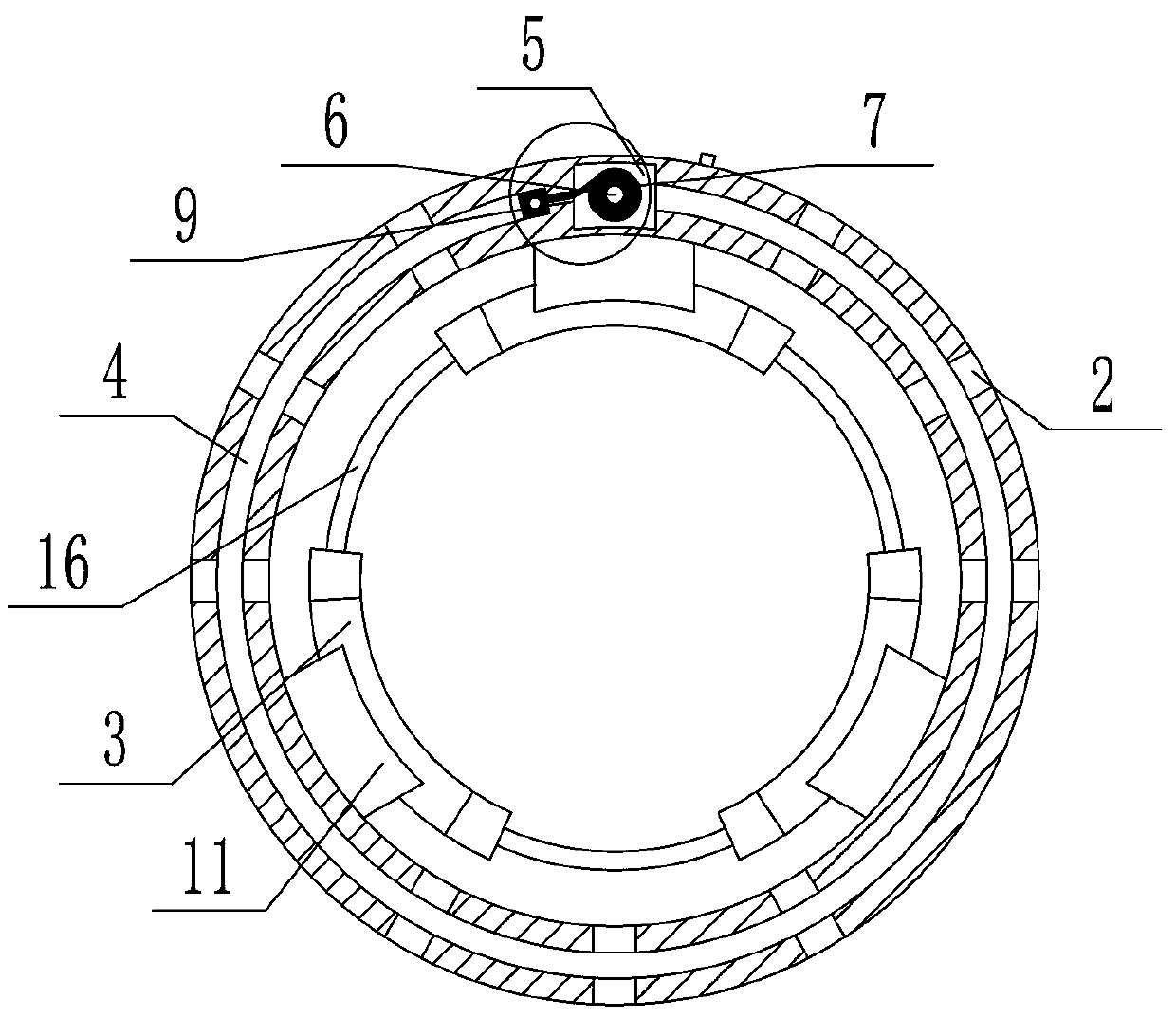
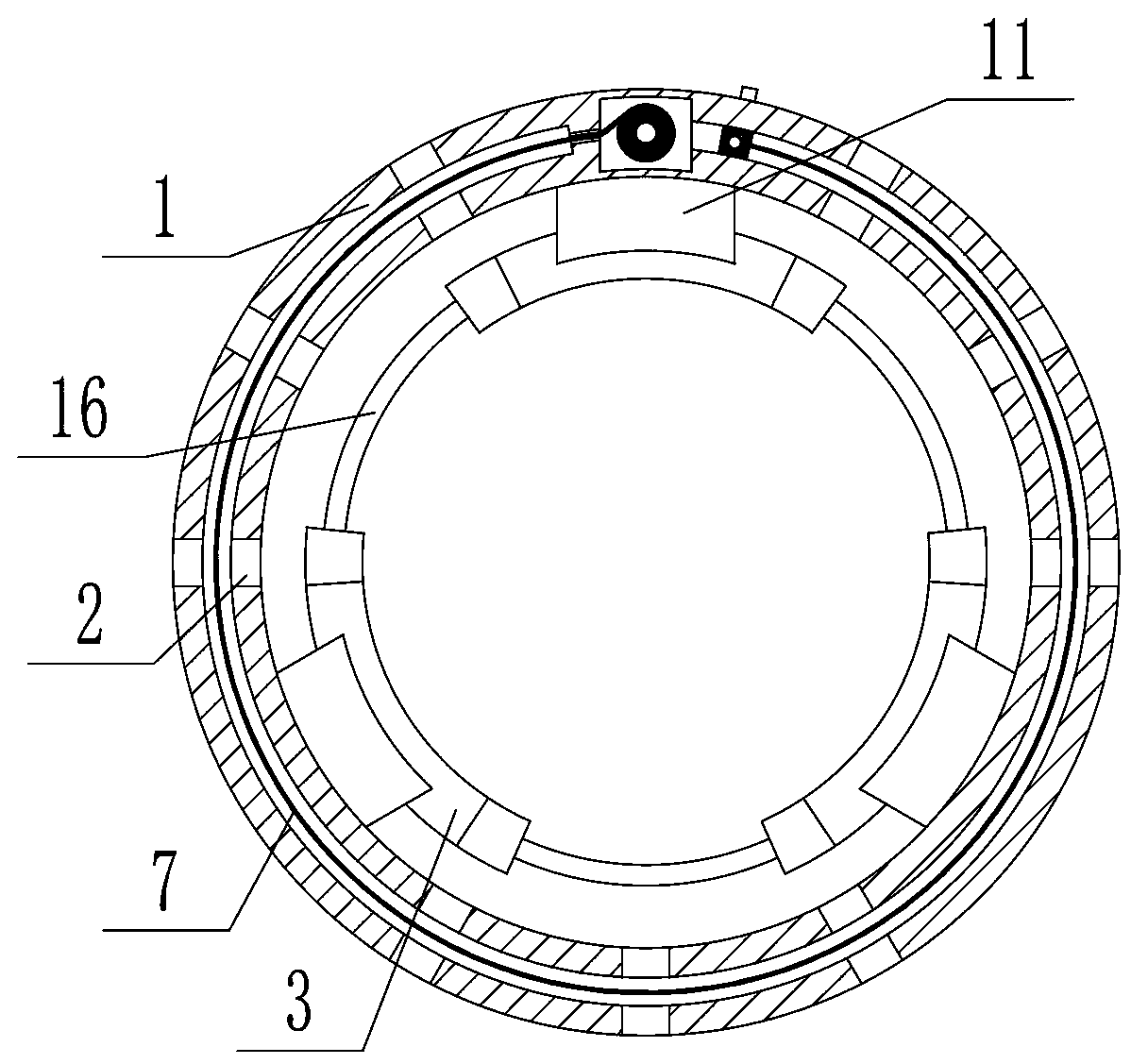
[0027] attached by Figure 1-9 It can be seen that the present invention includes a cylindrical outer cylinder body 1, the side wall of the outer cylinder body 1 is provided with a plurality of circumferentially evenly distributed air holes 2, and the inside of the outer cylinder body 1 is provided with a plurality of circumferentially uniformly distributed air holes 2. The arc-shaped guard plate 3 is connected by elastic strips 16 between every two adjacent arc-shaped guard plates 3, and the side wall of the outer cylinder 1 is provided with an annular groove 4, and the upper end of the annular groove 4 runs through The upper end surface of the outer cylinder body 1, the lower end of the annular groove 4 does not penetrate the lower end surface of the outer cylinder body 1, and the side wall of the outer cylinder body 1 is p...


PUM


Abstract

The invention relates to a fracture fixation protective device. The universality of different patients and the comfort level of the patients can be well improved; the relatively constant clamping force can be ensured; and furthermore, a breathable and protective effect can be taken on a diseased part. The fracture fixation protective device comprises an outer cylinder; the outer cylinder is provided with breathable holes; arc-shaped protective plates are arranged in the outer cylinder; every two adjacent arc-shaped protective plates are connected through an elastic strip; an annular groove isarranged in the side wall of the outer cylinder; an installation groove is arranged in the side wall of the outer cylinder; a rotating shaft is installed in the installation groove; a protective layersleeves the outer edge of a rotating shaft; a torsion spring is installed between the lower end of the rotating shaft and the outer cylinder; one end of the protective layer is fixedly connected withthe rotating shaft; the free end of the protective layer is connected to a vertical rib; the vertical rib is installed in the annular groove, and can rotate along the circumference of the annular groove; the vertical rib cannot enter the installation groove; a rotary body is installed on the upper end of the outer cylinder; and the rotary body rotates, so that the protective layer can be driven to rotate in the annular groove. The fracture fixation protective device in the invention is smart in conception and structure.

Description

technical field [0001] The invention relates to the technical field of medical auxiliary equipment, in particular to a fracture fixation and protection device. Background technique [0002] The finger is one of the common sites of fractures. If the finger fracture cannot be fixed in time and properly, it will seriously affect the healing speed, and even affect the recovery of finger function in the future, leaving sequelae. The traditional bandaging fixation method is to use bandages and splints or plaster fixation. This method is cumbersome to operate and requires professionals to implement, and there are great differences in the bandaging strength of different personnel, which is likely to bring pain to the injured. However, although the internal fixation method of the steel needle by the traditional operation is firm, the steel needle increases the secondary trauma, and requires a second operation to remove the steel needle after healing, and at the same time increases th...

Claims


Application Information

Patent Timeline
Patent Type & Authority Applications(China)
IPC IPC(8): A61F5/00A61F5/058
CPCA61F5/00A61F5/05875
Inventor 艾进伟韩叶萍
Owner HENAN PROVINCE HOSPITAL OF TCM THE SECOND AFFILIATED HOSPITAL OF HENAN UNIV OF TCM
Why Eureka
Try Eureka