Eureka AIR delivers breakthrough ideas for toughest innovation challenges, trusted by R&D personnel around the world.

Sealing structure of grouting stirring barrel of shield tunneling machine

A sealing structure and mixing tank technology, which is applied in cement mixing devices, shaft linings, tunnel linings, etc., and can solve problems such as the inability to arrange spare grouting mixing tanks and limited space

Inactive Publication Date: 2020-08-28
SHANGHAI TUNNEL ENG CO LTD
View PDF5 Cites 0 Cited by
  • Summary
  • Abstract
  • Description
  • Claims
  • Application Information

AI Technical Summary

Problems solved by technology

However, due to the limited space in the shield tunneling machine, usually most shield tunneling machines cannot arrange a spare grouting mixing tank. At this time, it is still impossible to avoid the impact of the grouting mixing tank on the construction

Method used


Image

  • Sealing structure of grouting stirring barrel of shield tunneling machine
  • Sealing structure of grouting stirring barrel of shield tunneling machine
  • Sealing structure of grouting stirring barrel of shield tunneling machine

Examples


Embodiment Construction

[0025] Embodiments of the present invention are described below through specific examples, and those skilled in the art can easily understand other advantages and effects of the present invention from the content disclosed in this specification. The present invention can also be implemented or applied through other different specific implementation modes, and various modifications or changes can be made to the details in this specification based on different viewpoints and applications without departing from the spirit of the present invention.

[0026] The present invention will be described in further detail below in conjunction with the accompanying drawings and specific embodiments.

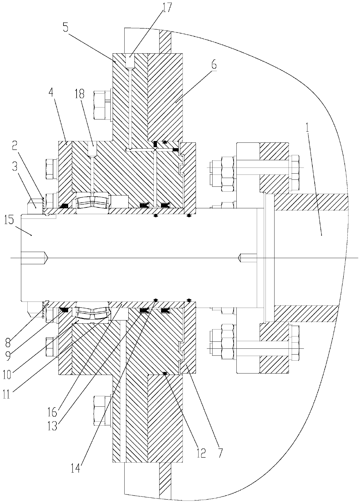
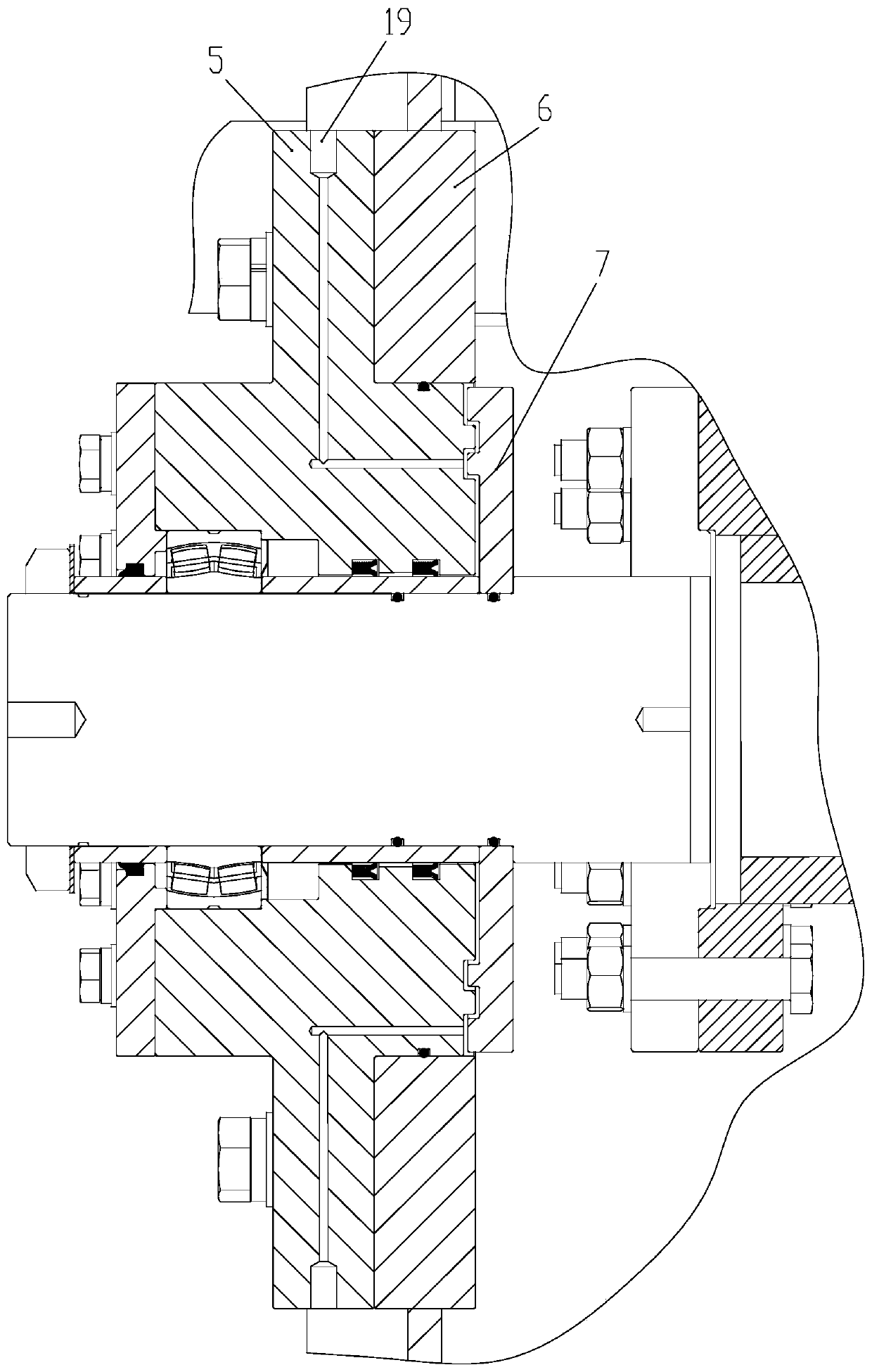
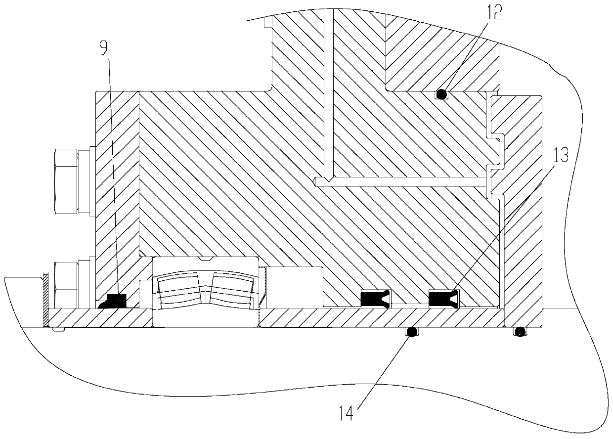
[0027] Such as Figure 1-5 As shown, the sealing structure of the grouting mixing barrel of the shield tunneling machine according to the embodiment of the present invention includes a transmission shaft 15, a sealing mounting seat 5, a bearing 10, a cover plate 7, a bearing outer ring baffle...


PUM


Abstract

The invention discloses a sealing structure of a grouting stirring barrel of a shield tunneling machine. The sealing structure comprises a transmission shaft, a seal mounting seat, a bearing, a coverplate, an outer bearing ring baffle plate and a plurality of oil filling passages, wherein a second perforating hole is formed in the outer bearing ring baffle plate; the outer bearing ring baffle plate is arranged on a first shaft sleeve in a sleeved mode through the second perforating hole and is arranged on the side, back away from the cover plate, of the seal mounting seat; a third sealing ring is arranged between an inner ring of the outer bearing ring baffle plate and the first shaft sleeve; and each oil filling passage comprises two first oil filling ports formed in the surfaces of thetwo opposite sides of an outer ring of the seal mounting seat and two first oil lines respectively communicating with the first oil filling ports, and the end, far away from the corresponding oil filling port, of each first oil line extends to an interface between the seal mounting seat and the cover plate. The sealing structure effectively reduces the phenomenon of slurry leakage of the groutingstirring barrel of the shield tunneling machine during working, eliminates the hidden trouble of slurry flowing into the bearing, and enables the tunnel construction to proceed smoothly.

Description

technical field [0001] The invention relates to the technical field of engineering machinery, in particular to a sealing structure of a grouting mixing barrel of a shield tunneling machine. Background technique [0002] When the grouting mixing tank of the existing shield tunneling machine is operated for a long time, the phenomenon of grout leakage usually occurs at the transmission shaft of the grouting mixing tank. When this phenomenon occurs, the slurry has usually entered the bearings of the drive shaft, which will cause damage to the bearings. Therefore, at this time, the tunnel construction needs to be stopped, the grouting mixing tank should be stopped, and the damaged bearing should be replaced. At the same time, the grout in the tank needs to be removed before it hardens. The whole process takes a long time and affects the construction progress. [0003] In order to reduce the impact of this phenomenon on construction, a plurality of grouting mixing barrels are us...

Claims


Application Information

Patent Timeline
Patent Type & Authority Applications(China)
IPC IPC(8): B28C5/08E21D9/06E21D11/10
CPCB28C5/0818E21D9/0607E21D11/105
Inventor 陈鼎屠垒袁向华翟一欣叶一舟吴文斐张雅澜顾旭莹严仁亮凌文倪美娜张陈昊费俊杰刘青苑范连
Owner SHANGHAI TUNNEL ENG CO LTD
Why Eureka
Eureka Blog
Learn More