Printing machine roller

A technology for printing machines and cleaning rollers, which is applied to printing machines, rotary printing machines, printing, etc., and can solve the problems of not being able to clean the edges of the machine rollers and the ink in the micropores, and achieve the effect of being easy to disassemble and wash

Active Publication Date: 2020-08-28
河北万杰机械科技股份有限公司
View PDF4 Cites 9 Cited by
  • Summary
  • Abstract
  • Description
  • Claims
  • Application Information

AI Technical Summary

Problems solved by technology

[0004] In order to make up for the deficiencies of the existing technology and solve the problems in the prior art that the ink in the micropores of the printing machine roll cannot be cleaned and the edge of the machine roll cannot be cleaned when the printing machine roll is working, a printing machine roll proposed by the present invention

Method used


Image

  • Printing machine roller
  • Printing machine roller
  • Printing machine roller

Examples


Embodiment approach

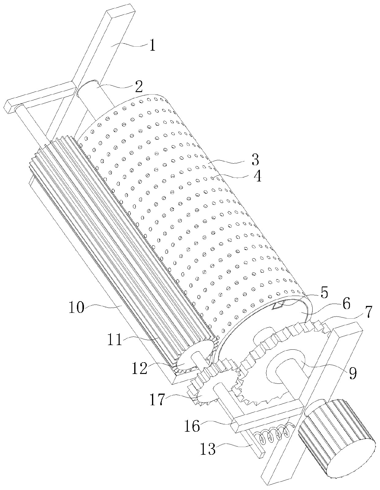
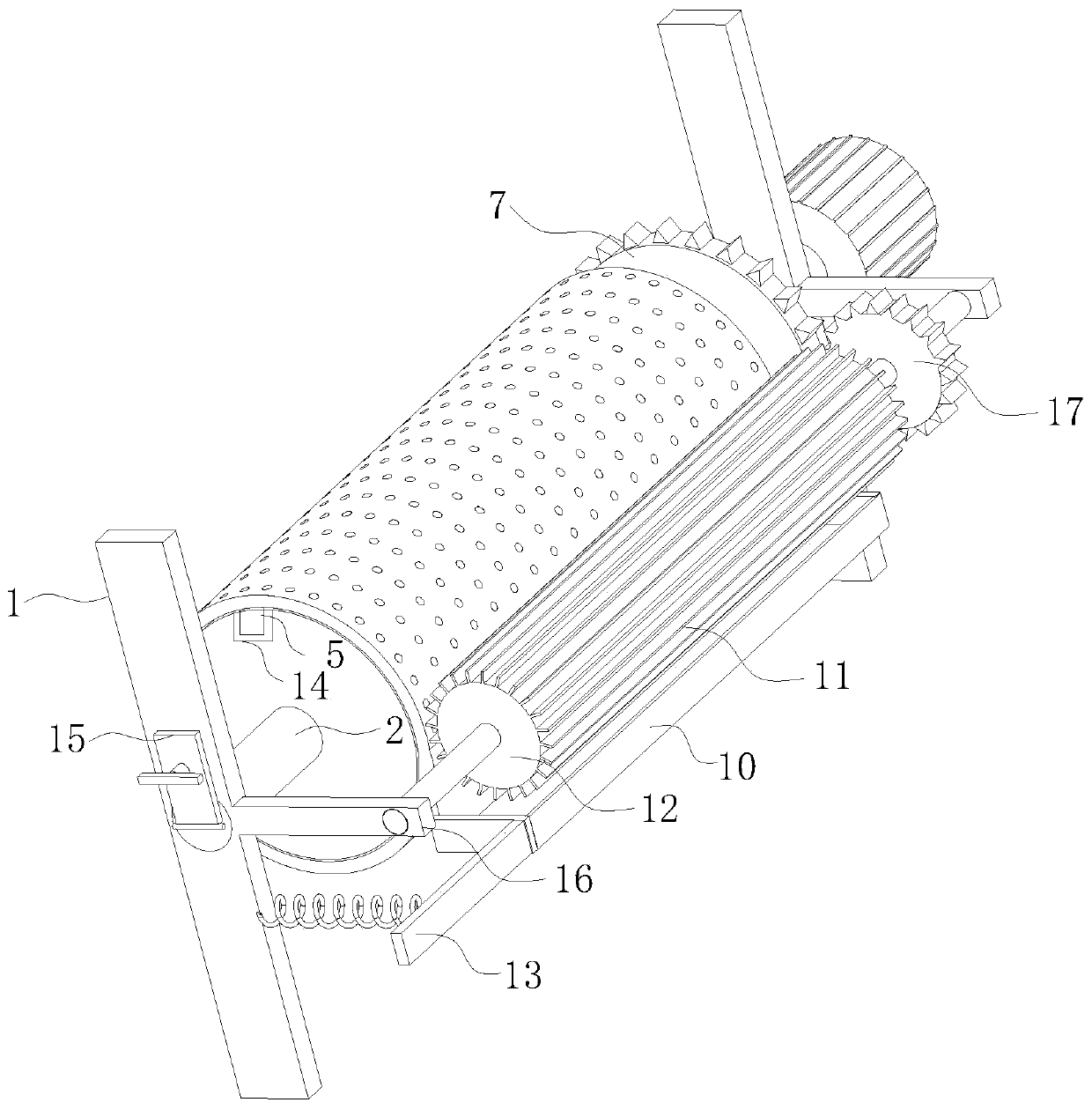
[0029] As an embodiment of the present invention, the rotating shafts at both ends of the cleaning roller 12 are movably connected to the horizontal mounting plate 16; one end of the horizontal mounting plate 16 is fixedly connected to the vertical support frame 1; the cleaning roller 12 An acceleration gear 17 is fixed on the rotating shaft close to the driving motor; the acceleration gear 17 is engaged with the active round gear 7 fixed on the rotating tube 2 for transmission; when working, the driving motor drives the rotating tube 2 to rotate, thereby driving the rotating tube 2 to rotate. The driving circular gear 7 on the tube 2 rotates, and the driving circular gear 7 drives the cleaning roller 12 to rotate through the engagement transmission with the acceleration gear 17, and since the rotating speed of the cleaning roller 12 is greater than the rotating speed of the outer casing 3, it is located at the edge of the cleaning roller 12 The rubber soft plate 11 can quickly...


PUM


Abstract

The invention belongs to the technical field of printing machines, and particularly provides a printing machine roller. The printing machine roller comprises a vertical supporting frame, a rotating pipe, an outer casing pipe, an inner driving pipe, an extrusion plate, a fixed rod, a rubber pipe and a rubber thin film, the inner wall of the outer casing pipe is provided with the inner driving pipein an attaching manner, the rubber thin film is mounted between the outer casing pipe and the inner driving pipe, micro holes are formed in the outer casing pipe and the inner driving pipe, a strip clamping block is fixedly mounted on the inner wall of the outer casing pipe and is clamped in a strip-shaped clamping groove in the outer edge of the inner driving pipe, the rubber pipe is fixedly bonded on the inner wall of the inner driving pipe, arc grooves are evenly formed in the outer edge of the rubber pipe, and communicate with the micro holes in the inner driving pipe, in the work processof a printing machine, the extrusion plate extrudes the rubber pipe on the inner side of the non work face of the outer casing pipe all the time, when the outer casing pipe rotates to the position ofthe non work face, the micro holes in the surface of the outer casing pipe are cleaned, and the micro holes of the outer casing pipe can be subjected to cleaning while the printing machine works.

Description

technical field [0001] The invention belongs to the technical field of printers, in particular to a printing machine roller. Background technique [0002] The printing efficiency of the roller printing machine is high, and it is widely used. In the existing roller printing machine, one side of the printing roller is immersed in the ink first, and the ink will adhere to the outer peripheral surface of the printing roller. Rotate to print the ink onto the paper or fabric. In order to ensure the printing quality, the fabric will be pressed against the printing roller by a rigid pressure roller during printing; some residual impurities will accumulate during the printing process of the existing printing roller. On the rubber surface of the printing roller, some of the residues can be cleaned with water or solvent, but there are still a small amount of impurities remaining at the bottom of the micropores on the rubber surface. These residues accumulate in the holes for a long ti...

Claims


Application Information

Patent Timeline
Patent Type & Authority Applications(China)
IPC IPC(8): B41F13/10B41F35/02
CPCB41F13/10B41F35/02B41P2235/10B41P2235/21B41P2235/22
Inventor 孟令霄程顺平
Owner 河北万杰机械科技股份有限公司
Why Eureka
Try Eureka