Middle pressure foot structure of sewing machine

A sewing machine and medium-pressure technology, which is applied in the direction of sewing machine components, cloth pressing mechanism, sewing equipment, etc., can solve problems such as complex structure, and achieve the effect of compact structure and convenient control

Pending Publication Date: 2020-08-28
NINGBO SUPREME ELECTRONIC MASCH INC
View PDF1 Cites 0 Cited by
  • Summary
  • Abstract
  • Description
  • Claims
  • Application Information

AI Technical Summary

Problems solved by technology

[0003] The technical problem to be solved by the present invention is to provide an intermediate presser foot structure of a sewing machine in view of the above-mentioned current state of the art, which can improve the defect that the traditional intermediate presser foot control motor is installed at the rear of the sewing machine head and has a complex structure, and simplify the control structure

Method used


Image

  • Middle pressure foot structure of sewing machine
  • Middle pressure foot structure of sewing machine
  • Middle pressure foot structure of sewing machine

Examples


Embodiment Construction

[0019] Embodiments of the present invention will be described in further detail below in conjunction with the accompanying drawings.

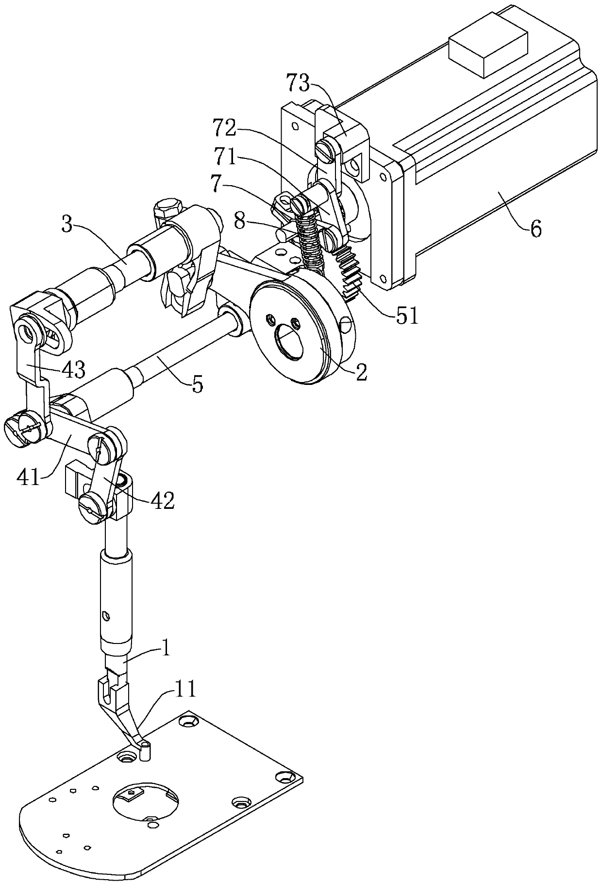
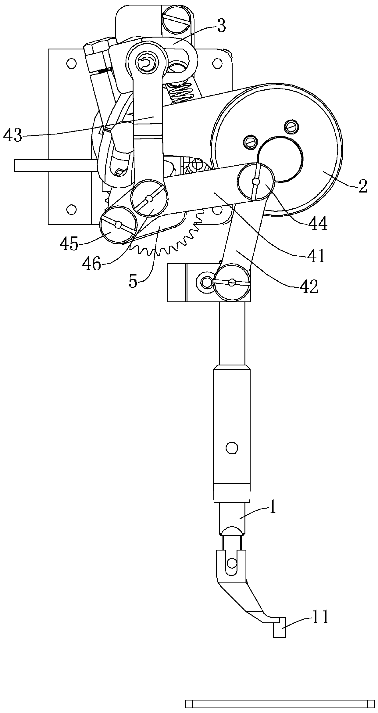
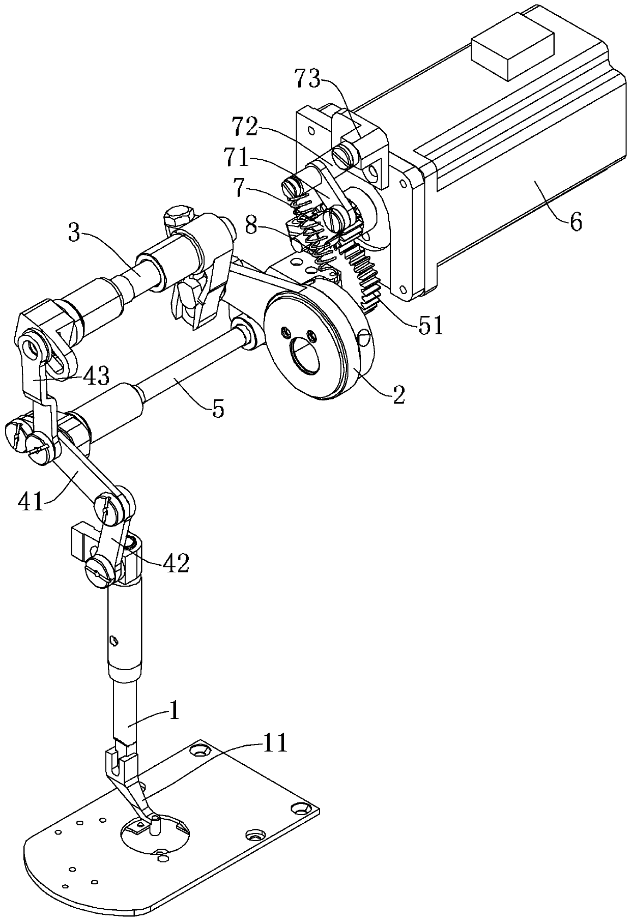
[0020] Figure 1 to Figure 5 Shown is the structural representation of the present invention.

[0021] The reference signs are: presser foot rod 1, intermediate presser foot 11, cam crank 2, eccentric cam 2a, sleeve part 2b, third crank part 2c, drive crank shaft 3, first straight rod part 3a, first Crank portion 3b, second crank portion 3c, first connecting rod 41, second connecting rod 42, third connecting rod 43, first rotating shaft 44, second rotating shaft 45, third rotating shaft 46, lifting control crank shaft 5, the first rotating shaft Two straight rod parts 5a, the fourth crank part 5b, transmission gear 51, induction plate 52, sensor 53, motor 6, power output shaft 61, power gear 62, reset crank 7, tight ring part 7a, the fifth crank part 7b, The fourth connecting rod 71 , the fifth connecting rod 72 , the first fixing seat 73 , t...


PUM


Abstract

The invention discloses a middle pressure foot structure of a sewing machine. The middle pressure foot structure comprises a middle pressure foot, a pressure foot bar, a cam crank connected to a spindle of the sewing machine, a transmission crank shaft connected to the cam crank and a connecting rod group connected to the pressure foot bar. The connecting rod group comprises a first connecting rod, wherein one end of the first connecting rod is movably connected to the pressure foot bar through a second connecting rod while the other end of the first connecting rod is rotatably connected to alift control crankshaft, a connecting hole is formed between two ends of the first connecting rod and the connecting hole is rotatably connected to the transmission crankshaft through a third connecting rod. The sewing machine is provided with a motor which controls the rotating angle of the lift control crankshaft.

Description

technical field [0001] The invention relates to an industrial sewing machine, in particular to an intermediate presser foot structure of the sewing machine. Background technique [0002] The utility model patent with the patent number of 201220078296.5 discloses a driving structure of the middle presser foot of a sewing machine, which includes a machine head and a presser foot bar connected with the presser foot. The drive mechanism, the second end of the pull rod is connected with the lifting rod that is rotatably arranged in the machine head, and the middle part of the lifting rod is matched with the rotation of the machine head through the support shaft; The lifting part is connected with the connecting rod seat; a triangular connecting plate is arranged on the connecting rod seat, and the triangular connecting plate is connected with the presser foot rod through the presser foot driving rod. In this patented technology, the tie rod extends from the front end of the mach...

Claims


Application Information

Patent Timeline
IPC IPC(8): D05B29/02D05B29/06
CPCD05B29/02D05B29/06
Inventor 胡小滨
Owner NINGBO SUPREME ELECTRONIC MASCH INC
Why Eureka
Try Eureka