
Oil bath type air filter

An air filter, oil bath type technology, applied in fuel air filter, combustion air/combustion-air treatment, machine/engine, etc., can solve the problem of low filtration efficiency, reduced oil filtration efficiency, and relatively low filtration efficiency Small and other problems, to achieve the effect of high filtration efficiency and low filtration efficiency

Pending Publication Date: 2020-08-28
无锡亿利环保科技有限公司 +1
View PDF1 Cites 2 Cited by
  • Summary
  • Abstract
  • Description
  • Claims
  • Application Information

AI Technical Summary

Problems solved by technology

[0005] The applicant aims at the low filtration efficiency of the above-mentioned existing oil bath air filter, especially in low temperature and low flow conditions, the filtration efficiency is greatly affected, and the lower oil wire assembly has more deposited oil droplets after being used for a long time, reducing In order to solve the shortcomings of oil filtration efficiency, provide an oil bath air filter with a reasonable structure, which has high filtration efficiency. Under low temperature and low flow conditions, the filtration efficiency is less affected, and the chassis of the lower oil wire assembly will not deposit oil. drop, to ensure oil filtration efficiency

Method used


Image

  • Oil bath type air filter
  • Oil bath type air filter
  • Oil bath type air filter

Examples


Embodiment Construction

[0044] The specific implementation manner of the present invention will be described below in conjunction with the accompanying drawings.

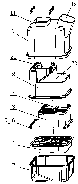
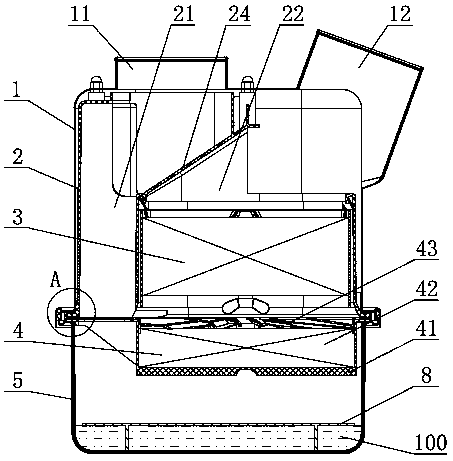
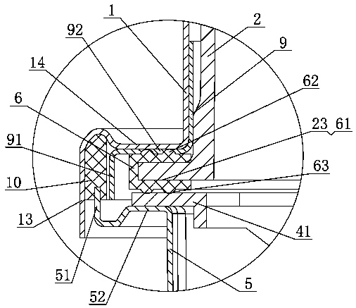
[0045] Such as figure 1 , figure 2 As shown, the upper casing 1 of the present invention is fixed on the lower casing 5 through a snap connection; the upper casing 1 is provided with a vertical air inlet 11 and an air outlet 12 inclined outward at a certain angle, and the upper casing 1 is fastened The parts are fixedly provided with an inner shell 2, and a seal is arranged between the inner shell 2 and the upper shell 1 to prevent gas blow-by in the gap between the inner shell 2 and the upper shell 1 and affect the filtering effect; the inner shell 2 has a partition 24 , the interior of the inner shell 2 is separated to form an air intake channel 21 and an air outlet channel 22, the air intake channel 21 communicates with the air inlet 11, the air outlet channel 22 communicates with the air outlet 12, and the air intake channel 21 and t...


PUM


Abstract

The invention discloses an oil bath type air filter. The oil bath type air filter is characterized in that a partition plate is arranged in an inner shell and divides the interior of the inner shell into an air inlet channel and an air outlet channel, an upper oil wire assembly is arranged in the air outlet channel, the upper portion of the partition plate inclines by a certain angle in the direction of the air outlet channel to form an inclined portion and a lower vertical portion, the inclined portion directly faces an air inlet, and a lower oil wire assembly is arranged in a lower shell. According to the oil bath type air filter, the partition plate of the inner shell forms the inclined portion and the vertical portion, the inclined portion directly faces the air inlet of an upper outershell, air flow enters an air flow direction-changing accelerating cavity from the air inlet and impacts the inclined plane of the inclined portion of the partition plate, part of impurities with large particles and heavy gravity in the air flow are primarily intercepted and filtered on the inclined plane, under the action of gravity of the impurities with large particles and heavy gravity or airflow pressure, the impurities slide down along the inclined plane and fall to the bottom of an inner cavity of the lower shell, and the air flow subjected to direction changing after impact is accelerated to enter the lower portion of the air inlet channel so that the impurities in the air flow can be more conveniently adsorbed and filtered through engine oil, and the filtering efficiency is higher.

Description

technical field [0001] The invention relates to the field of the air filter of the air intake system of an internal combustion engine, in particular to an oil bath type air filter. Background technique [0002] The oil bath air filter is usually used in the air intake system of the internal combustion engine to pre-filter the air entering the internal combustion engine and filter out the impurities in the air. The oil bath air filter mainly uses oil and metal wire filter layer as the main filter material. It uses air to hit the engine oil. After the oil mist is filtered, the relatively clean air is discharged, and then input to the next stage fine filter. [0003] Chinese utility model patent 201520534028.3 discloses an oil bath air filter, which includes an upper shell and a lower shell. The inner cavity of the housing is provided with an upper filter element assembly, and the side wall of the upper housing is provided with an air outlet. The air outlet is discharged thr...

Claims


Application Information

Patent Timeline
IPC IPC(8): F02M35/02F02M35/022F02M35/026F02M35/024
CPCF02M35/0201F02M35/0202F02M35/0216F02M35/0223F02M35/0226F02M35/02416F02M35/02466F02M35/026
Inventor 史忠可田传宝
Owner 无锡亿利环保科技有限公司
Learn More