Axisymmetric resonant gyroscope parameter excitation method based on discrete electrodes

A parametric excitation and resonant gyro technology, applied in the inertial field, can solve the difficulty of axisymmetric resonant gyroscope processing, cost and volume reduction, theoretical accuracy of axisymmetric resonant gyroscope, scale factor and dynamic range limitation, and precession characteristics can not be fully expressed Out of the problem, to avoid the phenomenon of standing wave azimuth binding, improve accuracy and performance, reduce the effect of power supply pressure

Active Publication Date: 2020-08-28
SHANGHAI AEROSPACE CONTROL TECH INST
View PDF7 Cites 0 Cited by
  • Summary
  • Abstract
  • Description
  • Claims
  • Application Information

AI Technical Summary

Problems solved by technology

At this time, the standing wave of the harmonic oscillator is bound, and the precession characteristics cannot be fully displayed. The theoretical accuracy, scale factor and dynamic range of the axisymmetric resonant gyroscope are all limited.
[0004] The current mainstream axially symmetric resonant gyroscope adopts a new system of two sets of electrode configurations. The two-piece configuration axisymmetrically symmetric resonant gyroscopes removes the excitation cover in the traditional three-piece configuration, and concentrates the excitation electrodes and detection electrodes on the base. , so that the processing difficulty, cost and volume of the axisymmetric resonant gyroscope are greatly reduced, but all electrodes are discrete electrodes, and the existing solutions can only use the position excitation method

Method used


Image

  • Axisymmetric resonant gyroscope parameter excitation method based on discrete electrodes
  • Axisymmetric resonant gyroscope parameter excitation method based on discrete electrodes
  • Axisymmetric resonant gyroscope parameter excitation method based on discrete electrodes

Examples


Embodiment Construction

[0028] The technical solutions of the present invention will be clearly and completely described below in conjunction with the accompanying drawings. Apparently, the described embodiments are some of the embodiments of the present invention, but not all of them. Based on the embodiments of the present invention, all other embodiments obtained by persons of ordinary skill in the art without making creative efforts belong to the protection scope of the present invention.

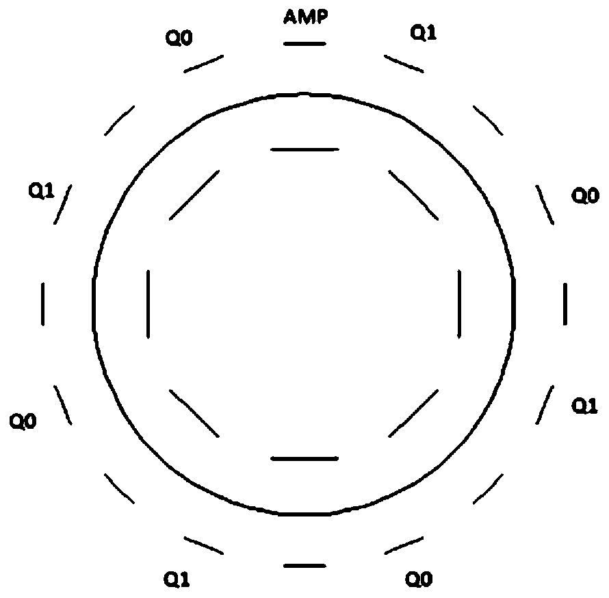
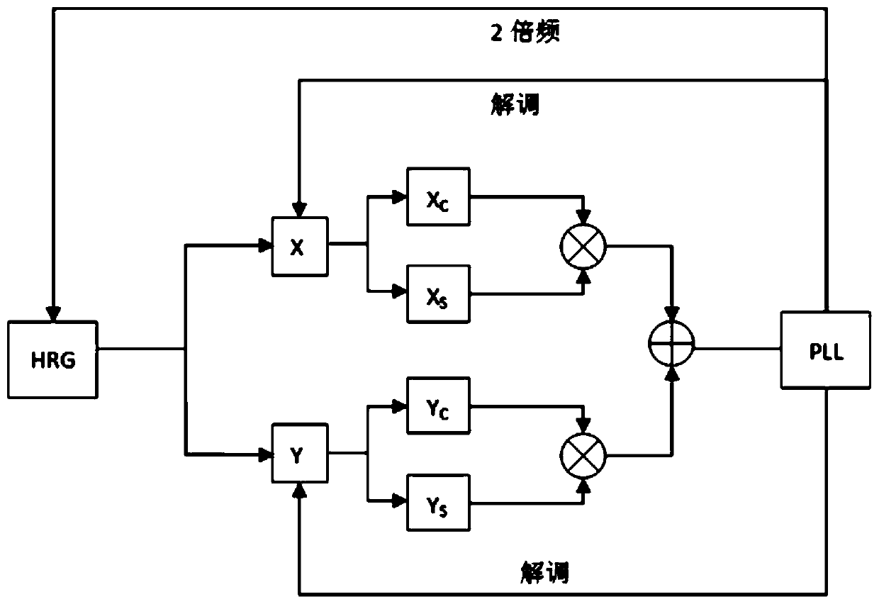
[0029] The "discrete electrodes" mentioned herein refer to the excitation electrodes discontinuously distributed on the axisymmetric hemispherical resonator gyroscope.

[0030] "Drive voltage" and "excitation voltage" are used interchangeably herein.

[0031] The meanings of "driving frequency" and "frequency of excitation voltage" and "excitation frequency" mentioned herein can be interchanged.

[0032] The invention is described below in conjunction with specific examples:

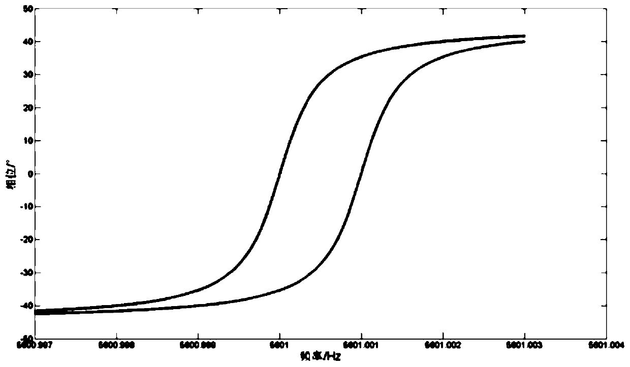
[0033] The positions of the n p...


PUM


Abstract

The invention discloses an axisymmetric resonant gyroscope parameter excitation method based on discrete electrodes. The method comprises the following steps: step 1, providing n excitation electrodeswhich are arranged on a hemispherical resonator gyro at intervals, and setting directions to meet the formula; step 2, applying a direct-current bias voltage and an excitation voltage to the excitation electrodes for parameter excitation, the frequency of the excitation voltage being twice of that of a resonator vibration signal, wherein the voltage applied to the ith excitation electrode is Vi =VbiasV0cos2omega lambda t; and step 3, adjusting the frequency of the excitation voltage and the amplitude of the excitation voltage to enable the frequency of the excitation voltage and the frequency of the excitation voltage to reach the minimum voltage and resonance frequency of parameter excitation, and enabling the amplitude of the excitation voltage to be the minimum value of the stable boundary voltage under harmonic oscillator parameter excitation. According to the invention, through the excitation of the discrete electrodes, the place with the maximum amplitude can obtain the maximumenergy supplement, and the energy supplement does not influence the standing wave orientation at the moment, thereby avoiding the binding phenomenon of the standing wave orientation caused by a conventional position excitation mode, and improving the precision and performance of the axisymmetric resonant gyroscope.

Description

technical field [0001] The invention relates to inertial technology, in particular to an axisymmetric resonant gyro parameter excitation method based on discrete electrodes. Background technique [0002] Axisymmetric resonant gyroscope is a new type of high-precision gyroscope instrument. The basic principle of detecting angular velocity is: the resonant oscillator generates a resonant standing wave under the excitation of the same frequency electrostatic energy of the excitation electrode. If the gyro body rotates relative to the inertial system, the standing wave will precess in the opposite direction. By detecting the precession angle, the rotation angle of the gyro body relative to the inertial system can be calculated. [0003] Axisymmetric resonant gyroscopes usually include three parts: excitation electrodes, resonators and detection electrodes. Excitation electrodes are used for amplitude control, quadrature control and force balance control. Currently, the positio...

Claims


Application Information

Patent Timeline
IPC IPC(8): G01C19/5776
CPCG01C19/5776
Inventor 赵万良刘付成杨浩李绍良王伟成宇翔
Owner SHANGHAI AEROSPACE CONTROL TECH INST
Why Eureka
Try Eureka