Shear nail anti-pulling test loading device used in cooperation with pressure testing machine

A pressure test and loading device technology, applied in measuring devices, using stable tension/pressure testing materials, instruments, etc., can solve problems that cannot be used to study shear nail cone failure, yield failure, etc. And the measurement process is convenient and fast, avoiding collision and jamming, and the effect of stiffness improvement

Active Publication Date: 2020-08-28
WENZHOU DESIGN ASSEMBLY CO LTD +2
View PDF9 Cites 0 Cited by
  • Summary
  • Abstract
  • Description
  • Claims
  • Application Information

AI Technical Summary

Problems solved by technology

The device applies tension by moving the hydraulic clamp downwards, but the lower surface of the concrete is in contact with the sleeve and cannot be used to study the cone failure of the shear stud
In addition, the section of the shear nail clamped by the hydraulic clamp is easy to yield and fail before other parts of the nail body

Method used


Image

  • Shear nail anti-pulling test loading device used in cooperation with pressure testing machine
  • Shear nail anti-pulling test loading device used in cooperation with pressure testing machine
  • Shear nail anti-pulling test loading device used in cooperation with pressure testing machine

Examples


Embodiment Construction

[0033] The present invention will be further described below in conjunction with the accompanying drawings and specific embodiments.

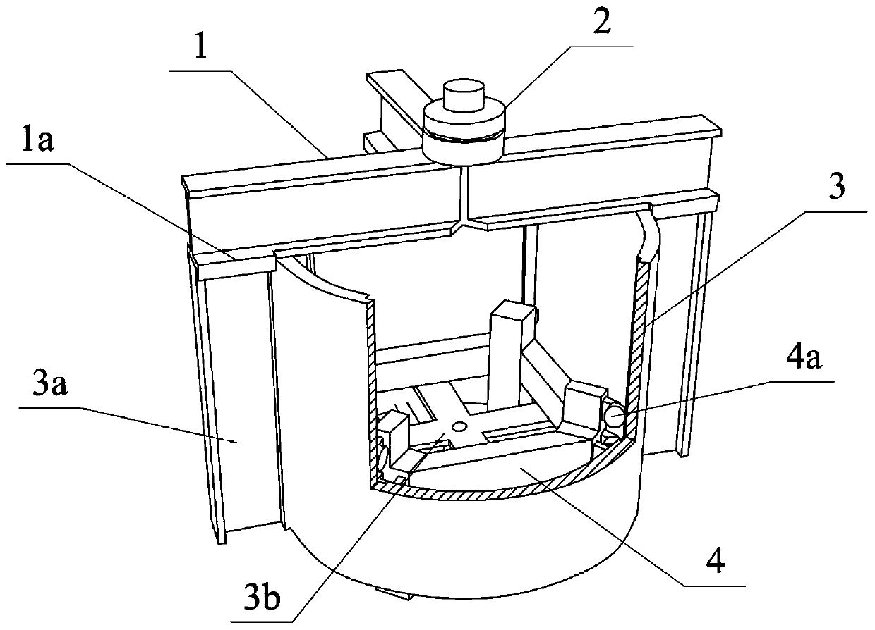
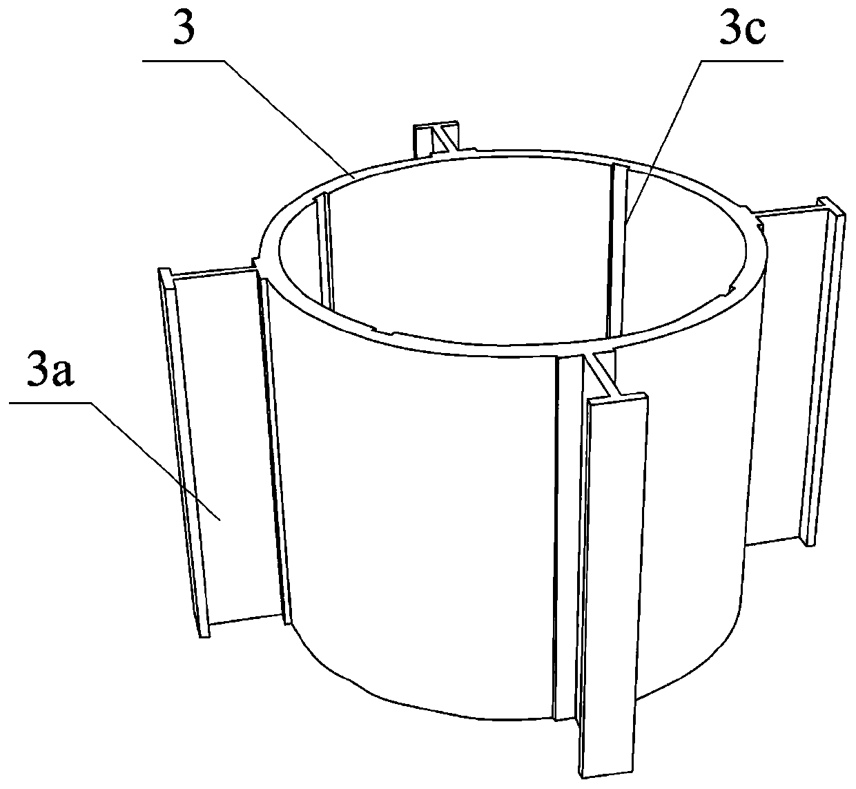
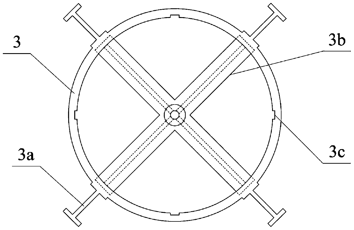
[0034] Such as Figure 1-9 As shown, a shear nail pull-out test loading device used in conjunction with a pressure testing machine includes a device body 3 which is hollow inside and a shelf 4 arranged inside it; the shelf 4 includes n legs, n≥3 , the upper parts of adjacent legs are connected by pillars to form an n-sided structure; the outer sides of the 4 legs of the storage rack are in sliding contact with the inner wall of the device body 3; the lower ends of the 4 legs of the storage rack protrude from the hollow bottom of the device body 3; On the frame 4, one end of the shear nail is buried in the concrete 6, and the other end protrudes from the bottom surface of the device body 3; one end of the shear nail protruding from the bottom surface of the device body 3 is provided with an external thread and a high-strength bolt 5; the loading...


PUM


Abstract

The invention discloses a shear nail anti-pulling test loading device used in cooperation with a pressure testing machine. The shear nail anti-pulling test loading device comprises a device body withthe hollow interior and a storage rack arranged in the device body. The storage rack comprises n supporting legs, n is larger than or equal to 3, and the upper portions of the adjacent supporting legsare connected through supporting columns to form an n-polygon structure. The outer sides of the storage rack supporting legs are in sliding contact with the inner wall of the device body; the lower ends of the storage rack supporting legs extend out of the hollowed-out bottom face of the device body; a concrete part is placed on the storage rack; one end of a shear nail is buried in the concrete,and the other end of the shear nail extends out of the bottom surface of the device body; external threads and high-strength bolts are arranged at one end, extending out of the bottom surface of thedevice body, of the shear nail; a loading head of the pressure testing machine is in contact with the upper end of the device body for loading pressure; the shear nail anti-pulling test loading deviceis simple in structure, reasonable in stress, clear in force transmission, capable of meeting the use requirements of all shear nail static anti-pulling tests, convenient and fast in loading and measuring process, high in measured data precision, free of calibration and capable of meeting the safety requirements at the same time.

Description

technical field [0001] The invention relates to bridge engineering, in particular to a shear nail pullout test loading device used in conjunction with a pressure testing machine. Background technique [0002] Steel-concrete composite structure is a structural form developed on the basis of concrete structure and steel structure. Reinforced concrete components and steel components are combined through connectors, so that concrete and steel work together to bear force and give full play to their respective material advantages. The composite structure has the advantage of light weight, which reduces the seismic response. At the same time, the problem of concrete cracking is alleviated through reasonable stress. Some steel members can be used as concrete formwork, which greatly simplifies the construction process and shortens the construction period. The composite structure can reduce the amount of steel used, and With greater rigidity and better stability. Therefore, steel-con...

Claims


Application Information

Patent Timeline
Patent Type & Authority Applications(China)
IPC IPC(8): G01N3/08G01N3/02
CPCG01N3/08G01N3/02G01N2203/0003G01N2203/0019G01N2203/0252G01N2203/0682
Inventor 谢明化占玉林赵硕硕沈东胡逸凡贾银钧王龙张龙
Owner WENZHOU DESIGN ASSEMBLY CO LTD
Why Eureka
Try Eureka