A kind of ultra-high power laser for communication and its preparation method
An ultra-high power, laser technology, applied in the direction of lasers, semiconductor lasers, phonon exciters, etc., can solve the problems affecting the integration density of the optical path of the silicon optical integrated module, affecting the transmission capacity of a single optical module, etc.
- Summary
- Abstract
- Description
- Claims
- Application Information
AI Technical Summary
Problems solved by technology
Method used
Image
Examples
Embodiment 1
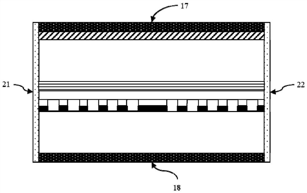
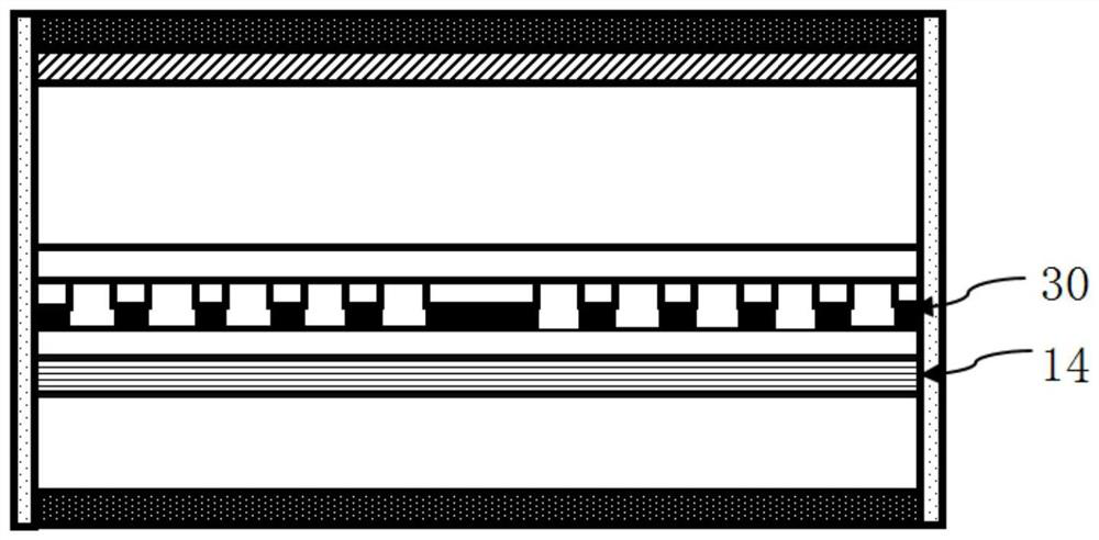
[0044] Embodiment 1: The grating layer is arranged below the active layer (bottom grating), and the material of the grating diffraction layer is In 1-x Ga x As y P 1-y Among them, x=0.33, y=0.75; Diffraction grating layer thickness D g =50nm; first cladding thickness D c =100nm; second cladding thickness D b =100nm; phase shift grating width W p =1.5*Λ; the position ratio R of the phase shift grating p = 0.5. refer to Figure 7a , compared to the traditional top grating (the grating layer is placed above the active layer, see figure 2 ), its output optical power is increased by 40%, which fully meets the requirements of the silicon photonics integration scheme for the output power of the laser above 70mW.
Embodiment 2
[0045] Embodiment 2: Using the bottom grating structure, the material of the grating diffraction layer is In 1-x Ga x As y P 1-y Among them, x=0.07, y=0.15; Diffraction grating layer thickness D g =50nm; first cladding thickness D c =100nm; second cladding thickness D b =100nm; phase shift grating width W p =1.5*Λ; the position ratio R of the phase shift grating p = 0.5.
Embodiment 3
[0046] Embodiment 3: as Figure 7a As shown, using the bottom grating structure, the grating diffraction layer material composition In 1-x Ga x As y P 1-y Among them, x=0.55, y=0.85; Diffraction grating layer thickness D g =50nm; first cladding thickness D c =100nm; second cladding thickness D b =100nm; phase shift grating width W p =1.5*Λ; the position ratio R of the phase shift grating p = 0.5.
[0047] Figure 7b It is the laser output power curve of different grating diffraction layer material components. All three components can achieve the output power requirement of more than 70mW, but the optimal values are x=0.33, y=0.75;
PUM
| Property | Measurement | Unit |
|---|---|---|
| thickness | aaaaa | aaaaa |
| thickness | aaaaa | aaaaa |
| thickness | aaaaa | aaaaa |
Abstract
Description
Claims
Application Information
 - R&D
- Intellectual Property
- Life Sciences
- Materials
- Tech Scout
- Unparalleled Data Quality
- Higher Quality Content
- 60% Fewer Hallucinations
Browse by: Latest US Patents, China's latest patents, Technical Efficacy Thesaurus, Application Domain, Technology Topic, Popular Technical Reports.
© 2025 PatSnap. All rights reserved.Legal|Privacy policy|Modern Slavery Act Transparency Statement|Sitemap|About US| Contact US: help@patsnap.com


