
Motor model prediction current control method and device, electronic equipment and medium

A technology for predicting current and control method, applied in the direction of motor generator control, AC motor control, control of electromechanical transmission devices, etc. The effect of the zone configuration

Active Publication Date: 2020-08-28
NORTH CHINA UNIVERSITY OF TECHNOLOGY
View PDF8 Cites 2 Cited by
  • Summary
  • Abstract
  • Description
  • Claims
  • Application Information

AI Technical Summary

Problems solved by technology

[0004] In view of this, the purpose of one or more embodiments of this specification is to propose a motor model predictive current control method and device, electronic equipment and media to solve the problem of the existence of the dead zone and the role of the zero vector among the candidate vectors. It will lead to the existence of high-amplitude common-mode voltage, which will affect the service life of the motor
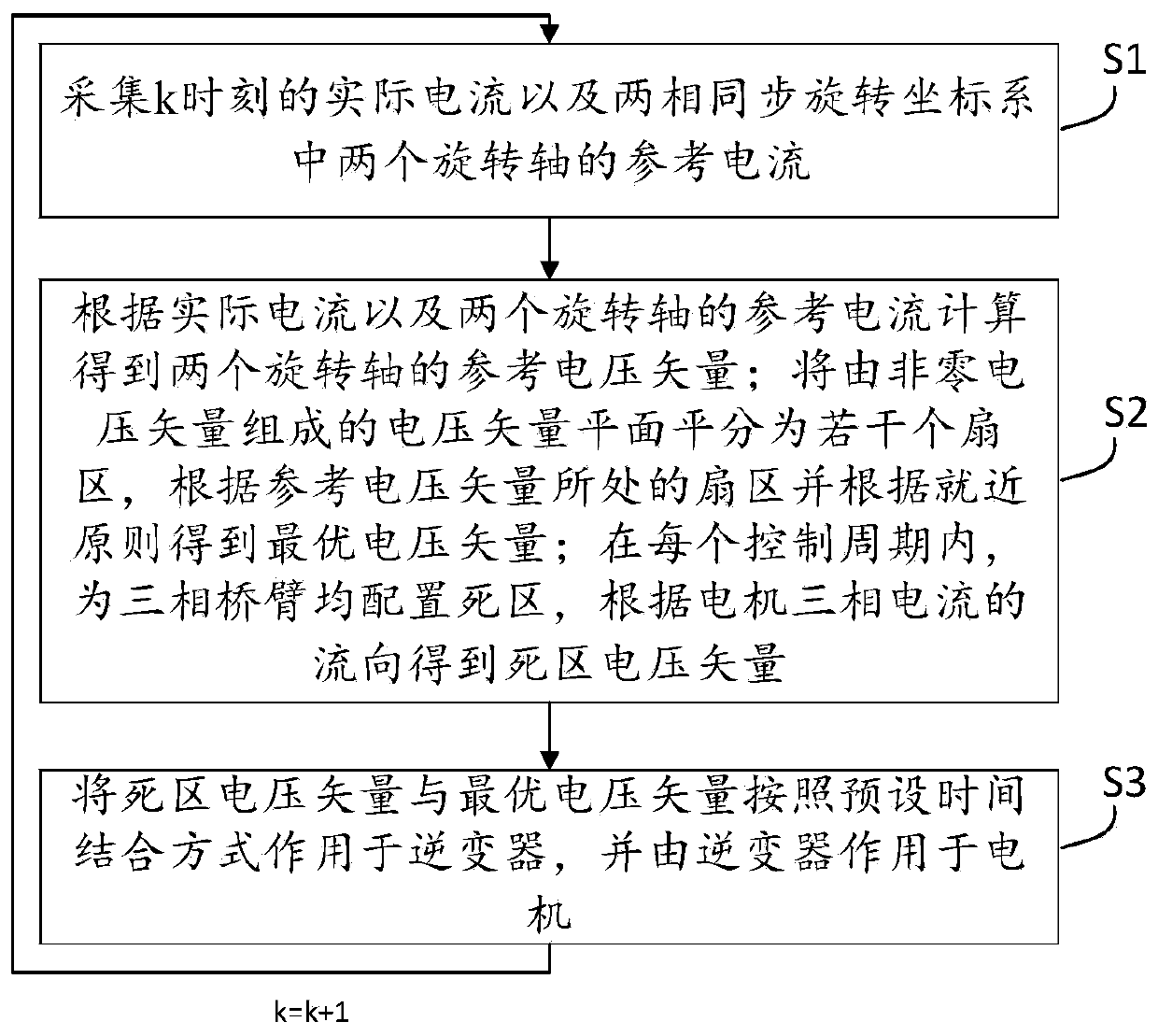
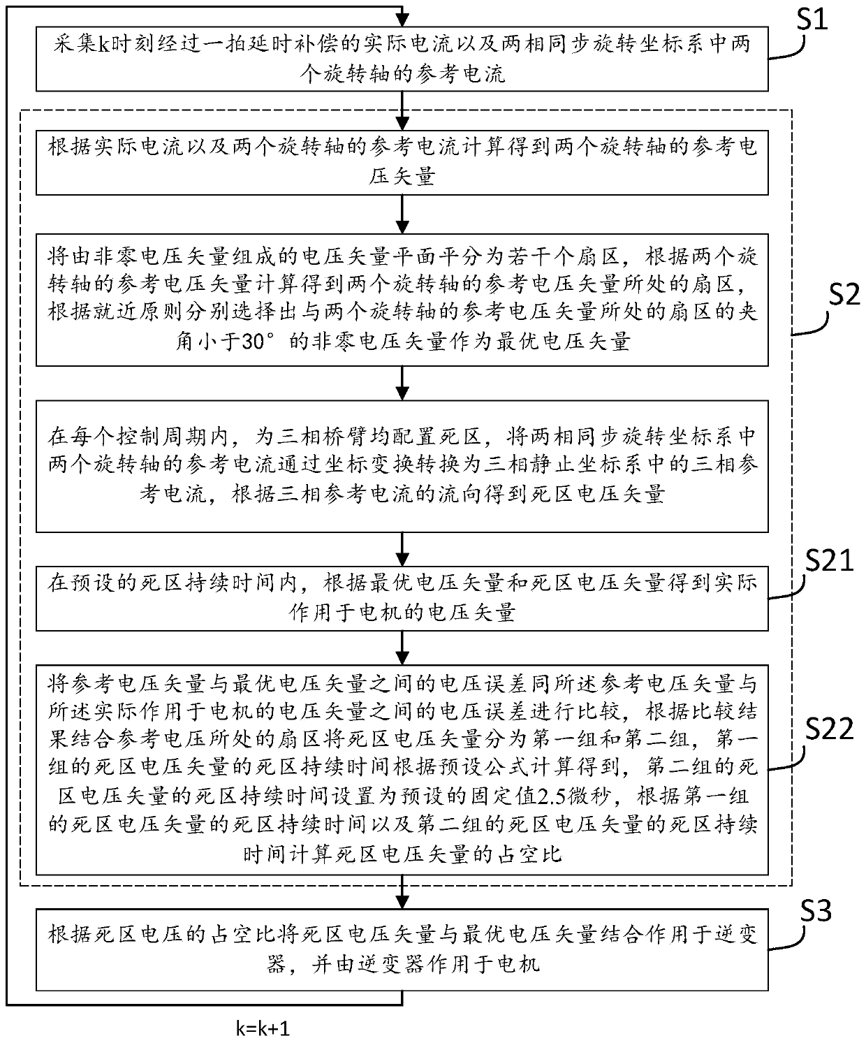
This method selects the optimal voltage vector from non-zero voltage vectors according to the principle of proximity after obtaining the sector where the reference voltage vector is located by means of fast vector selection, and configures a dead zone for each inverter bridge arm, according to The dead-zone voltage vector is obtained from the flow direction of the three-phase current of the motor, which solves the influence of the high-amplitude common-mode voltage generated by the equivalent zero vector of the dead-zone voltage vector and the zero vector in the vector to be selected on the life of the motor, and the dead-zone voltage Vector duration is optimized as a variable for improved control

Method used


Image

  • Motor model prediction current control method and device, electronic equipment and medium
  • Motor model prediction current control method and device, electronic equipment and medium
  • Motor model prediction current control method and device, electronic equipment and medium

Examples


Embodiment Construction

[0042] In order to make the purpose, technical solutions and advantages of the present disclosure clearer, the present disclosure will be further described in detail below in conjunction with specific embodiments and with reference to the accompanying drawings.

[0043] It should be noted that, unless otherwise defined, the technical terms or scientific terms used in one or more embodiments of the present specification shall have ordinary meanings understood by those skilled in the art to which the present disclosure belongs. "First", "second" and similar words used in one or more embodiments of the present specification do not indicate any order, quantity or importance, but are only used to distinguish different components. "Comprising" or "comprising" and similar words mean that the elements or items appearing before the word include the elements or items listed after the word and their equivalents, without excluding other elements or items. Words such as "connected" or "con...


PUM


Abstract

One or more embodiments of the invention provide a motor model prediction current control method and device, electronic equipment and a medium. According to the method, an optimal voltage vector is selected from non-zero voltage vectors according to the principle of proximity after a sector where a reference voltage vector is located is obtained in a fast vector selection mode; a dead zone is configured for each inverter bridge arm; the dead-zone voltage vector is obtained according to the flow direction of the three-phase current of a motor; the influence of the high-amplitude common-mode voltage generated by the zero vector equivalent to the dead-zone voltage vector and the zero vector in the to-be-selected vectors on the service life of the motor is solved; and the dead-zone voltage vector duration is used as a variable for optimization, and the control effect is improved.

Description

technical field [0001] One or more embodiments of this specification relate to the technical field, and in particular to a motor model predictive current control method and device, electronic equipment and media. Background technique [0002] Among the control strategies of AC motor speed control system, the most mature one is vector control. In the vector control method, the outer loop controls the speed and the inner loop controls the current. First, the rotor position angle and the stator current measured by the Hall are collected through the encoder, and then the three-phase stationary coordinate system is transformed into a two-phase rotating coordinate system through coordinate transformation, and then the voltage space vector pulse width modulation (SVPWM) is used to ) technology acts on the inverter to control the motor. Vector control has a good steady-state effect, but the dynamic effect is average, and there are three PI regulators, which increases the difficult...

Claims


Application Information

Patent Timeline
Patent Type & Authority Applications(China)
IPC IPC(8): H02P21/22H02P21/14H02P21/00H02P27/12H02M7/5387H02M7/5395H02M1/38
CPCH02M1/38H02M7/53875H02M7/5395H02P21/0017H02P21/14H02P27/12H02P21/22H02M1/385H02M7/53876
Inventor 张晓光程昱
Owner NORTH CHINA UNIVERSITY OF TECHNOLOGY
Learn More