
Photovoltaic power generation device with flexible support

A photovoltaic power generation and photovoltaic power generation panel technology, which is applied to photovoltaic power generation, photovoltaic modules, solar thermal power generation, etc. Effects of pressure, reduced horizontal thrust, and extended service life

Active Publication Date: 2020-08-28
嘉兴技师学院
View PDF13 Cites 4 Cited by
  • Summary
  • Abstract
  • Description
  • Claims
  • Application Information

AI Technical Summary

Problems solved by technology

[0006] Aiming at the above-mentioned shortcomings existing in the prior art, the present invention provides a photovoltaic power generation device with a flexible support, which can effectively overcome the prefabricated photovoltaic power generation panel support structure existing in the prior art, and the photovoltaic power generation panel cannot Adjust according to the angle of the sun. At the same time, after long-term use of photovoltaic power generation panels, a lot of dust will stick to them. When there is a lot of dust, it is easy to affect the power generation efficiency of photovoltaic power generation panels.

Method used


Image

  • Photovoltaic power generation device with flexible support
  • Photovoltaic power generation device with flexible support
  • Photovoltaic power generation device with flexible support

Examples


Embodiment 1

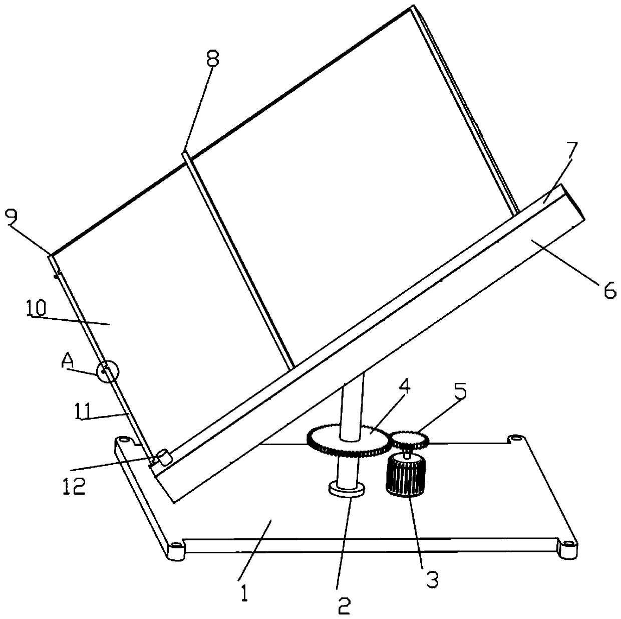
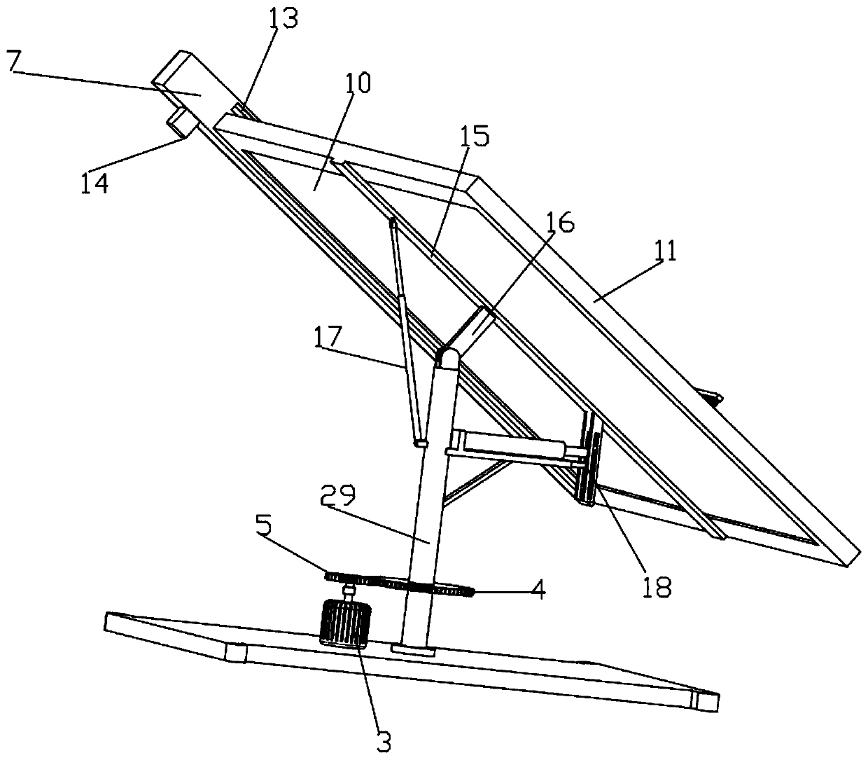
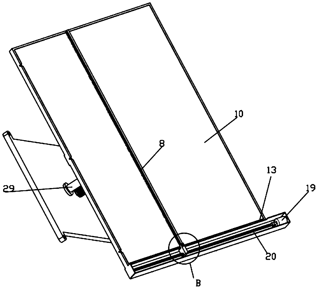
[0035] Such as Figure 1-7A photovoltaic power generation device with a flexible support is shown, including a bottom plate 1, a first drive motor 3 and a photovoltaic power generation panel 10, the top of the bottom plate 1 is fixedly connected with a bearing 2 and a first drive motor 3, and the output of the first drive motor 3 The end is fixedly connected with the active ring gear 5, the inner ring of the bearing 2 is fixedly connected with the straight rod 29, the side wall of the straight rod 29 is fixedly connected with the driven ring gear 4, the driven ring gear 4 and the driving ring gear 5 are engaged and connected, and the straight rod 29 tops are rotatably connected with a rotating plate 16, the top of the rotating plate 16 is fixedly connected with a connecting plate 15, and the left and right ends of the straight bar 29 are respectively fixedly connected with a stable structure 17 for connecting the connecting plate 15 and for adjusting the angle of the connecting...

Embodiment 2

[0038] Embodiment 2 is a further improvement to Embodiment 1.

[0039] Such as Figure 1-7 A photovoltaic power generation device with a flexible support shown includes a bottom plate 1, a first drive motor 3 and a photovoltaic power generation panel 10, the top of the bottom plate 1 is fixedly connected with a bearing 2 and a first drive motor 3, and the first drive motor 3 The output end is fixedly connected with the driving ring gear 5, the inner ring of the bearing 2 is fixedly connected with the straight rod 29, and the side wall of the straight rod 29 is fixedly connected with the driven ring gear 4, and the driven ring gear 4 and the driving ring gear 5 are meshed and connected. The top of the bar 29 is rotatably connected with a rotating plate 16, the top of the rotating plate 16 is fixedly connected with a connecting plate 15, and the left and right ends of the straight bar 29 are respectively fixedly connected with a stable structure 17 for connecting the connecting ...

Embodiment 3

[0041] Embodiment 3 is a further improvement to Embodiment 1.

[0042] Such as Figure 1-7 A photovoltaic power generation device with a flexible support shown includes a bottom plate 1, a first drive motor 3 and a photovoltaic power generation panel 10, the top of the bottom plate 1 is fixedly connected with a bearing 2 and a first drive motor 3, and the first drive motor 3 The output end is fixedly connected with the driving ring gear 5, the inner ring of the bearing 2 is fixedly connected with the straight rod 29, and the side wall of the straight rod 29 is fixedly connected with the driven ring gear 4, and the driven ring gear 4 and the driving ring gear 5 are meshed and connected. The top of the bar 29 is rotatably connected with a rotating plate 16, the top of the rotating plate 16 is fixedly connected with a connecting plate 15, and the left and right ends of the straight bar 29 are respectively fixedly connected with a stable structure 17 for connecting the connecting ...


PUM


Abstract

The invention relates to the technical field of photovoltaic power generation. The invention discloses a photovoltaic power generation device with a flexible support. Bottom plate, the bottom plate isprovided with a bearing and a first driving motor; the first driving motor is provided with a driving gear ring; straight rod of bearing, the straight rod is provided with a driven gear ring; the driven gear ring is connected with the driving gear ring; straight rod rotating plate, connecting plate of rotating plate, the straight rod is provided with a stable structure and an angle adjusting structure; supporting frame of connecting plate, groove is formed in supporting frame, the support frame is connected with the photovoltaic power generation panel through the groove; the photovoltaic power generation panel is provided with an insertion block; groove is provided with a slot, the inserting blocks are inserted into the inserting grooves; second spring of supporting frame, insertion rod of second spring, the inserting rods are inserted into the inserting blocks; the supporting frame is provided with an outer cover, the outer cover is provided with a second driving motor, the second driving motor is provided with a threaded rod, the threaded rod is provided with an L-shaped sliding plate, and the top face and the bottom face of the outer cover are fixedly provided with a photosensitive sensor and a controller correspondingly.

Description

technical field [0001] The invention relates to the technical field of photovoltaic power generation, in particular to a photovoltaic power generation device with a flexible support. Background technique [0002] As an important energy component in the 21st century, solar photovoltaic power generation will become the main body of the world's energy supply. It is estimated that by 2030, renewable energy will account for more than 30% of the total energy structure, and solar photovoltaic power generation will account for more than 10% of the world's total power supply; More than 50% of energy consumption, solar photovoltaic power generation will account for more than 20% of total electricity; by the end of the 21st century, renewable energy will account for more than 80% of the energy structure, and solar power will account for more than 60%. These figures are enough to show the development prospects of the solar photovoltaic industry and its important strategic position in t...

Claims


Application Information

Patent Timeline
Patent Type & Authority Applications(China)
IPC IPC(8): H02S20/30H02S30/10H02S40/10F24S30/425B08B1/00
CPCH02S20/30H02S30/10H02S40/10F24S30/425B08B1/12Y02E10/47Y02E10/50
Inventor 郑晓辉张天林卞超群邱林军童晓星余国周哲杰
Owner 嘉兴技师学院
Learn More