An orthopedic arthroscopic wire passing device

An arthroscopic and orthopedic technology, applied in applications, surgical instruments, etc., can solve the problems of easy falling off, inconvenient use of surgical tools, and various surgical tools, so as to avoid loss, simple and practical disinfection operation, and reduce the difficulty of operation

Active Publication Date: 2021-06-18
HENAN PROVINCE HOSPITAL OF TCM THE SECOND AFFILIATED HOSPITAL OF HENAN UNIV OF TCM
View PDF7 Cites 0 Cited by
  • Summary
  • Abstract
  • Description
  • Claims
  • Application Information

AI Technical Summary

Problems solved by technology

[0006] Aiming at the deficiencies of the prior art, the present invention provides an orthopedic arthroscopic thread-passing device, which effectively solves the technical problems of a large number of surgical tools used in the existing arthroscopic surgery, the threading sutures are easy to fall off, and the surgical tools are inconvenient to use.

Method used


Image

  • An orthopedic arthroscopic wire passing device
  • An orthopedic arthroscopic wire passing device
  • An orthopedic arthroscopic wire passing device

Examples


Embodiment 2

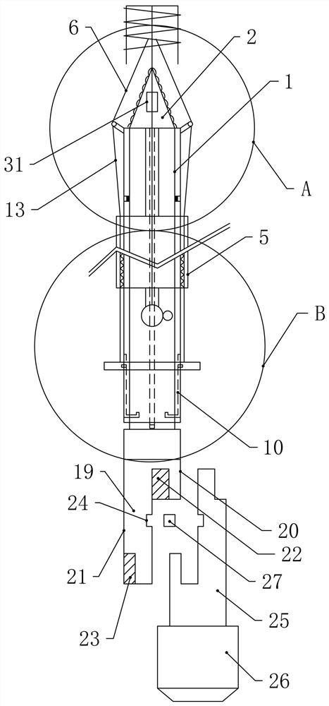
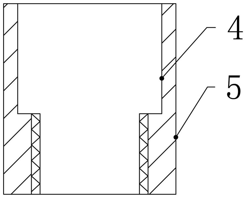
[0065] Embodiment 2, in particular, a ring-shaped slider one 15 is fixed to the inner side wall of the sleeve 4, and the slider one 15 can be rotated in the slide rail. To ensure that the cylinder is rotated in normal rotation, the sleeve is not rotated.

Embodiment 3

[0066] Example III, in particular, the rotation of the drill plate 7 requires a rotating portion, the rotation portion mounted a bracket 16 that matches the number of drills 7 in the outer wall of the sleeve 4, that is, there are 4, the bracket 16 is An angled tilt setting is attached to the end of the bracket 16, and a shaft piece 7 is fixed to the shaft portion 17, and the shaft shaft one 17 is connected to the shaft 9, and the coaxial 17 is provided with a coaxial spring 18.

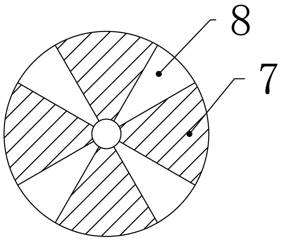
[0067] When using, when the drill piece 7 is placed outside the spiral turnt head 2, a spacing 8 is left between each of the two drill pieces 7, and the tip of the drill 7 is circular. The circle is relatively small, does not affect the drilling, and the coil spring 18 at this time makes the drill 7 have a pressing force in the direction of the spiral turnt head 2. When the drill piece 7 is pulled, the reel spring 18 begins to be affected. Force status.

Embodiment 4

[0068] Example 4, in particular, the length of the drill table 7 is greater than the length of the spiral turnt head 2 such that the drill 7 can be wrapped in the spiral turnt head 2 (not completely sealed), and the end of the upper end of the sleeve 2 5 The distance between the end to the upper end of the sleeve 4 is greater than the length of the drill piece 7.

[0069] As such, the spiral turnt head 2 is placed in the drill bit 6, and when the drill block 7 is pulled, the drill table 7 starts flipping, and the diamonds 7 after the flipping drill 7 have not been exposed to the sleeve 2 5, and the subsequent drill pieces 7 enters The inner side wall of the sleeve is prepared.


PUM


Abstract

The invention relates to an arthroscopic thread threading device for orthopedics, which effectively solves the technical problems of the existing arthroscopic surgery using many surgical tools, easy threading and mending, and inconvenient use of surgical tools, including: cylinder one, spiral rotor , the screw head is installed on one end of the cylinder one, and the two sides of the screw head are provided with helical patterns; the sleeve one, the cylinder one rotates in the sleeve one; the sleeve two, the sleeve two is set in the sleeve The outside of cylinder one; the drill bit, the drill bit is composed of multiple drill pieces with a circular cross-section, the pulling device, the pulling device includes a pulley, and the outer end of sleeve one is provided with two opposite T-shaped slots, where the sleeve The outer side of the first sleeve is provided with a pull ring placed on the outer end of the second sleeve. The inner side of the pull ring is fixed with a slider placed in a T-shaped slot. A pull rope is wound on the pulley, and the other end of the pull rope passes through the second sleeve. The side wall is connected to the pull ring, and the invention can be produced and manufactured, and obtains corresponding positive effects, and is practical.

Description

Technical field [0001] The present invention relates to the field of orthopedic surgery, in particular an orthopedic arthroscope. Background technique [0002] The arthroscope is a rod-like optical instrument that observes the diameter of about 5 mm in the joint inner structure, which is an endoscope for diagnosing the joint disease. The arthroscope is equipped with a lens in the end of a thin tube, insert the thin tube into the interior, and the internal structure inside the joint will be displayed on the monitor. Therefore, the internal structure can be directly observed. Arthroscopic is not only used for diagnosis of disease, but also is widely used in the treatment of joint diseases. [0003] Many surgery in orthopedics will be used in arthroscopy. For example, in the patient's shoulder-sleeve repair surgery, the arthroscopy is used, and in this bulk lip repair surgery, its main repair principle is to use the surgical rope. The tapped ligament is repeated to restore the ligam...

Claims


Application Information

Patent Timeline
Patent Type & Authority Patents(China)
IPC IPC(8): A61B17/04
CPCA61B17/0469A61B17/0482
Inventor 冯丽娜王上增
Owner HENAN PROVINCE HOSPITAL OF TCM THE SECOND AFFILIATED HOSPITAL OF HENAN UNIV OF TCM
Why Eureka
Try Eureka