Cutting device for electronic mainboard production

A technology of cutting device and main board, which is applied to the separation of dispersed particles, the use of liquid separating agent, metal processing, etc. It can solve the problems of high dust concentration in the production workshop, lower cutting precision, easy shaking and displacement, etc., to improve cutting stability, Improve stability and reduce the effect of air pollution

Inactive Publication Date: 2020-09-01
邹龙龙
View PDF8 Cites 2 Cited by
  • Summary
  • Abstract
  • Description
  • Claims
  • Application Information

AI Technical Summary

Problems solved by technology

[0003] The present invention proposes a cutting device for the production of electronic motherboards, which solves the problem that the existing electronic motherboards will generate higher temperatures during the cutting process and lead to a higher dust concentration in the production workshop, and cannot be effectively fixed during the cutting operation. , so that it is easy to shake and shift during cutting, reducing the cutting accuracy

Method used


Image

  • Cutting device for electronic mainboard production
  • Cutting device for electronic mainboard production
  • Cutting device for electronic mainboard production

Examples


Embodiment 1

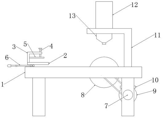
[0025] Embodiment 1: When the device is in use, the electronic main board to be processed is first placed between two clamping plates 2 for clamping, and then the threaded rod 4 is rotated so that the threaded rod 4 pushes the pressing plate 5 to move downward, thereby making The electronic main board to be processed can be limited and fixed in the horizontal and vertical directions to prevent it from shifting during the cutting process.

Embodiment 2

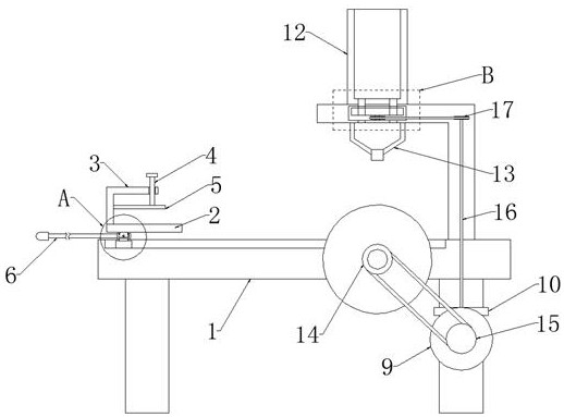
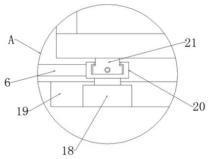
[0026] Embodiment 2: In the above embodiment, after the electronic main board is limited and fixed, the horizontal plate 20 can be moved by holding the push rod 6, so that the horizontal plate 20 drives the movable block 18 to slide inside the movable groove 19, thereby driving the placement of the splint 2 and Place the electronic main board on the splint 2 to move to the cutting disc 8, then start the driving motor 7, so that the driving motor 7 drives the first main pulley 15 and the main gear plate 9 to rotate, and the first main pulley 15 drives the first secondary pulley 14 through the transmission belt Rotate, the first secondary pulley 14 drives the cutting disc 8 to rotate again, so that the cutting disc 8 performs cutting operation on the electronic main board, and the main gear disc 9 drives the secondary gear disc 10 to rotate, and the secondary gear disc 10 drives the connecting rod 16 and the second main pulley 17 rotates, and the second main pulley 17 drives the ...


PUM


Abstract

The invention discloses a cutting device for electronic mainboard production, and relates to the field of electronic mainboard production. The cutting device aims at solving the problems that in the existing electronic mainboard cutting process, high temperature can be generated, the dust concentration of a production workshop is large, in the cutting operation process, the electronic mainboard cannot be effectively fixed, and therefore shaking and displacement are likely to happen during cutting, and the cutting precision is reduced. According to the following scheme, the cutting device comprises an operation table, wherein two symmetrically-distributed supporting plates are fixedly arranged at the bottom end of the operation table; two symmetrically-distributed movable grooves are formedin the top end of the operation table in the length direction of the operation table; and movable blocks are arranged in the movable grooves in a sliding manner. According to the cutting device, an electronic mainboard to be machined can be effectively limited and fixed, the stability during electronic mainboard cutting is improved, meanwhile, a cutting disc in the cutting process can be cooled,dust falling treatment can be carried out on the workshop environment, and guarantees are provided for safety of production workers.

Description

technical field [0001] The invention relates to the field of electronic mainboard production, in particular to a cutting device for electronic mainboard production. Background technique [0002] During the production and processing of electronic motherboards, the raw materials need to be cut to make them suitable for production size. However, the traditional electronic motherboards cannot be effectively fixed during the cutting operation, so that the motherboard is easy to shift during the cutting process, resulting in cutting The problem of lower precision, and high temperature and dust will be generated during the cutting process, which will make the contact between the main board and the cutting board easy to melt and deform, and will also cause environmental pollution in the workshop and endanger the health of workers. Therefore, in order to solve such problems, we A cutting device for the production of electronic motherboards is presented. Contents of the invention ...

Claims


Application Information

Patent Timeline
Patent Type & Authority Applications(China)
IPC IPC(8): B26D7/02B26D7/08B01D47/06B26D7/06B26D1/15B26D5/08
CPCB01D47/06B26D1/15B26D5/086B26D7/025B26D7/0608B26D7/08
Inventor 邹龙龙
Owner 邹龙龙
Why Eureka
Try Eureka