Small water surface cleaning ship with flow guide device

A technology for a diversion device and a cleaning boat, which is applied to the cleaning of the open water surface, the load handling device, the hull, etc., can solve the problems of complicated collection and unloading process, small harvesting area, and high use cost, and achieves a simple setting method, The effect of increasing the collection width and ensuring the sailing speed

Pending Publication Date: 2020-09-01
FEICHI ENVIRONMENTAL PROTECTION TECH INC CO LTD
View PDF1 Cites 2 Cited by
  • Summary
  • Abstract
  • Description
  • Claims
  • Application Information

AI Technical Summary

Problems solved by technology

[0004] 1. The water on the surface of the floating object cannot be fully drained, resulting in poor endurance of the drifter;
[0005] 2. The harvesting device and the setting of the conveyor belt not only cause the structure to be complicated, but also the process of collecting and unloading is also very complicated, resulting in high cost of use and low work efficiency
In order to solve the above technical problems, in the patent No. ZL201610844092.0 (water surface cleaning ship with self-flowing collection of floating objects on the water surface), a gap is opened in the bow of the hull, and an installation groove connected with the gap is opened in the middle of the hull. The storage cabin in the tank is installed, so that the harvesting process is easy to operate and the cleaning efficiency is improved. However, in the harvesting process, the limitation is relatively large and the harvesting area is small. At the same time, in the normal driving process, Due to the existence of gaps, the resistance of the cleaning ship is relatively large. How to solve the above technical problems is something that those skilled in the art are committed to solving.

Method used


Image

  • Small water surface cleaning ship with flow guide device
  • Small water surface cleaning ship with flow guide device
  • Small water surface cleaning ship with flow guide device

Examples


Embodiment Construction

[0022] The technical solutions of the present invention will be further described below in conjunction with the accompanying drawings and specific embodiments.

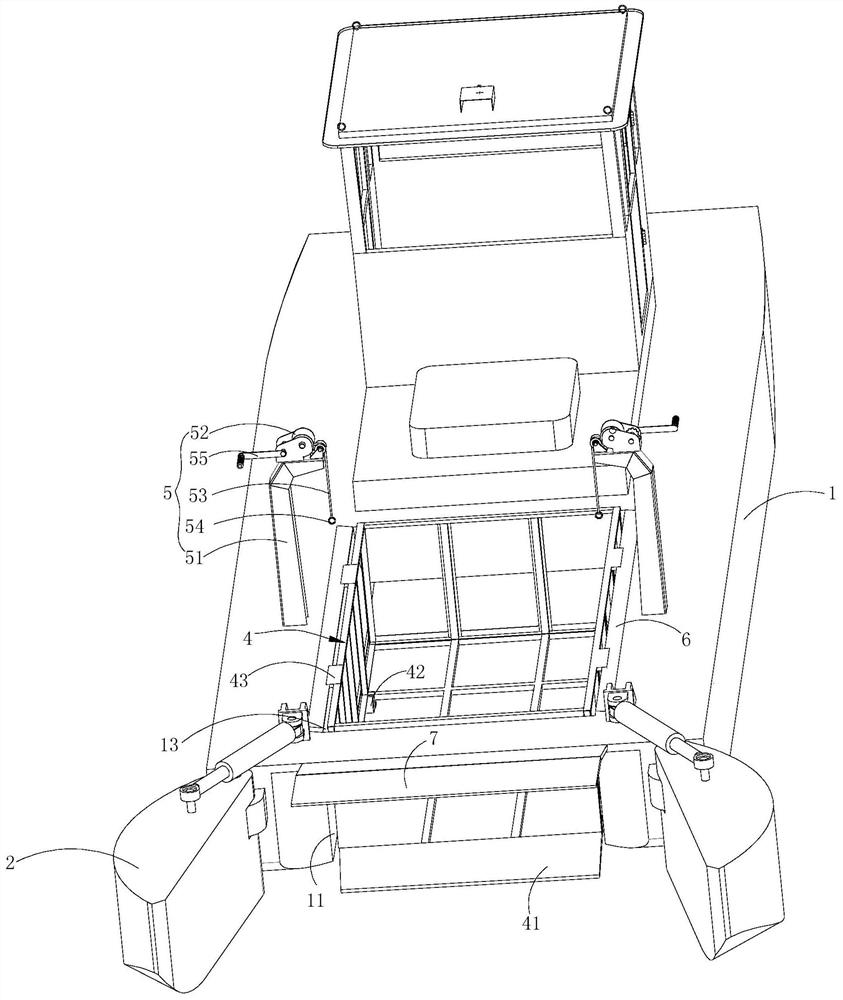
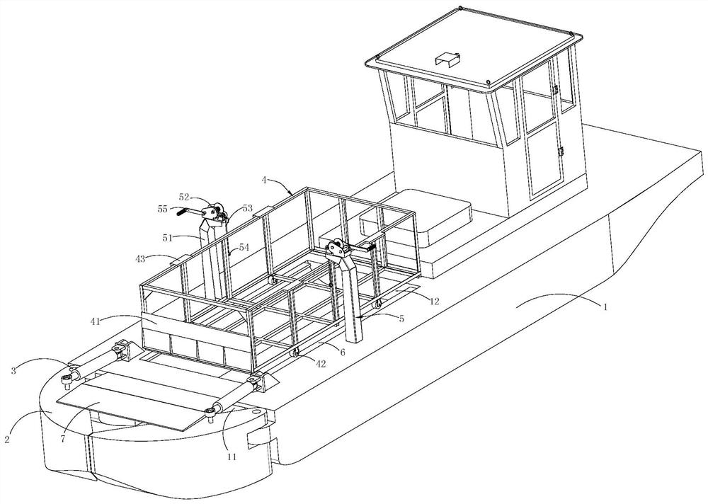
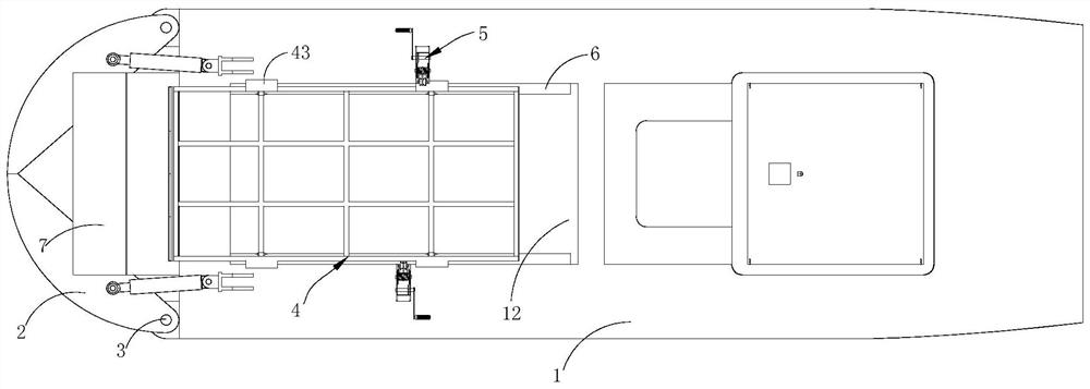
[0023] A small water surface cleaning boat equipped with diversion devices, see figure 1 , 2 As shown, including the hull 1, the bow of the hull 1 is provided with a gap 11, and the middle part of the hull 1 is provided with a recovery tank 12 communicating with the gap 11, and a flow guiding device is also installed on the hull 1.

[0024] The deflector includes a pair of mirror-symmetric deflectors 2, one end of the deflector 2 is installed on the front end of the hull 1 through a rotating shaft 3 arranged in the vertical direction, and the other end is a free end. The flow plate 2 is respectively arranged on the left and right sides of the gap 11, see figure 1 , 2 As shown, the deflector has two working states of unfolding and closing. When harvesting floating objects, the two deflectors 2 rotate outwards away f...


PUM


Abstract

The invention discloses a small water surface cleaning ship with a flow guide device, which comprises a ship body. A notch is formed in the head part of the ship body; a harvesting groove communicatedwith the notch is formed in the middle of the ship body; the ship body is further provided with a flow guide device, the flow guide device comprises a pair of flow guide plates in mirror symmetry, the two flow guide plates are arranged on the left side and the right side of the notch respectively, the flow guide device has an unfolded working state and a closed working state, and when floaters are collected, the two flow guide plates deviate from each other and rotate outwards, and at the moment, the flow guide device is in the unfolded state; when harvesting is finished and normal sailing iscarried out, the two flow guide plates rotate inwards till the free ends of the two flow guide plates abut against each other and shield the front end of the notch, and at the moment, the flow guidedevice is in a closed state. The device is simple in structure, plays a role in guiding garbage and increasing the collection width, can reduce resistance borne by the ship body in the normal sailingprocess, and ensures the sailing speed.

Description

technical field [0001] The invention relates to a water surface cleaning ship, in particular to a small water surface cleaning ship equipped with a flow guiding device. Background technique [0002] In recent years, with the aggravation of water eutrophication, the research on aquatic plant harvesting projects has attracted more and more attention from all over the world. With the wanton littering of domestic garbage, the pollution of rivers will seriously affect the health of surrounding residents, especially In scenic spots, floating objects can be seen everywhere, so the use of drift cleaning boats is very common, and its styles are also very diverse. [0003] For different areas of use and types of floating objects, different cleaning boats are used. Especially the cleaning boats used in scenic spots, most of them pass through the harvesting device at the bow, and then transfer to the storage cabin through the conveyor belt, so there are obvious shortcomings: [0004] ...

Claims


Application Information

Patent Timeline
IPC IPC(8): B63B35/32B63B1/40B63B25/00E02B15/10
CPCB63B1/40B63B25/002B63B35/32E02B15/10Y02T70/10
Inventor 吴橙高磊刘剑青钱云飞时俊意倪云鑫茅雨峰郭苏浩朱天野
Owner FEICHI ENVIRONMENTAL PROTECTION TECH INC CO LTD
Why Eureka
Try Eureka