Automatic cup covering device
A cup-covering and automatic technology, which is applied in packaging and other directions, can solve the problems of large volume of cup-covering machines, and achieve the effects of small size, reduced cost, and reduced occupied area.
- Summary
- Abstract
- Description
- Claims
- Application Information
AI Technical Summary
Problems solved by technology
Method used
Image

Examples
Embodiment 1
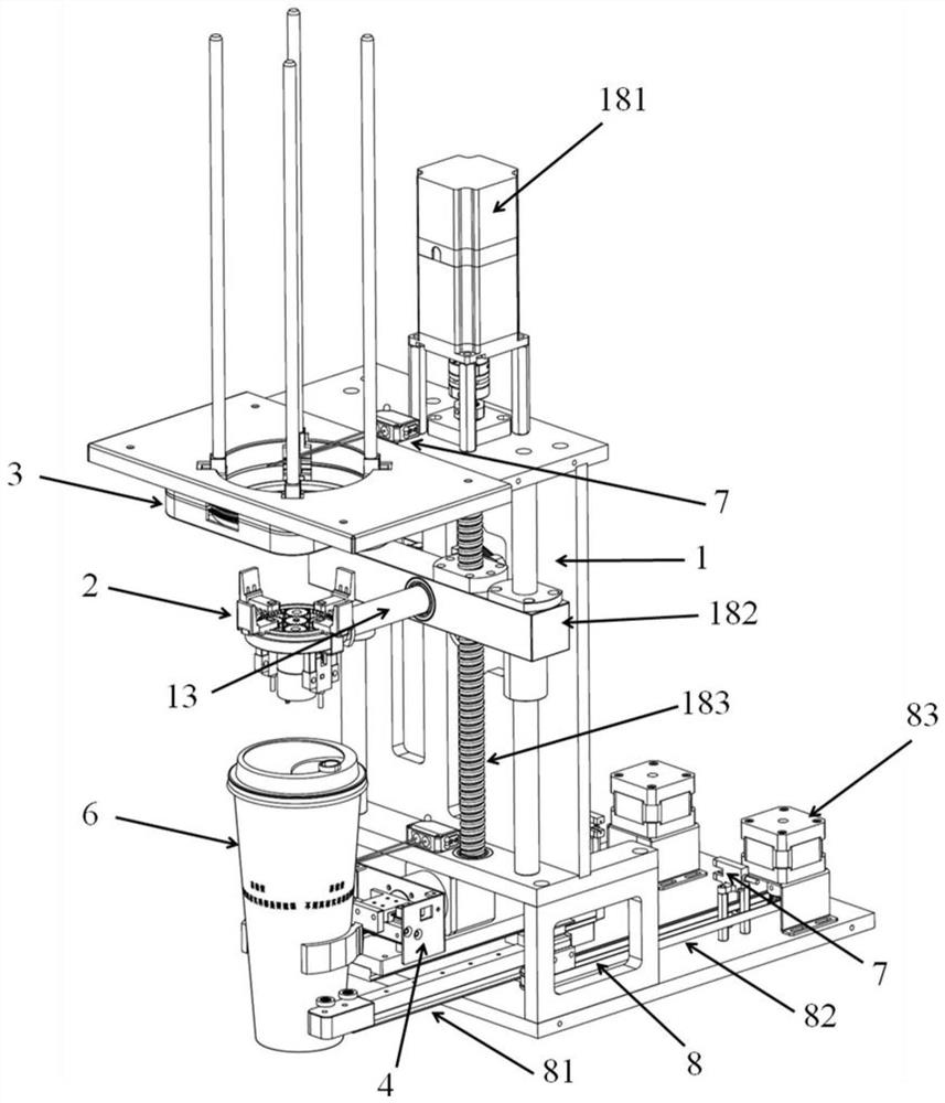
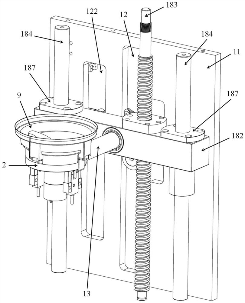
[0028] like Figure 1 to Figure 3 As shown, an automatic cup cover device of the present invention includes a cup cover output mechanism 3 for storing the cup cover 9, a cup cover grabbing mechanism 2, a cup cover claw rotation mechanism 1, and the cup cover grabbing mechanism 2 is connected to the cup On the lid claw rotating mechanism 1, the cup lid ejecting mechanism 3 is set at the station above the cup lid grabbing mechanism 2, and there is a station for placing the cup body below the cup lid grabbing mechanism, and the cup lid claw rotating mechanism 1 drives the cup lid grabbing The picking mechanism 2 moves between the upper and lower stations, and at the same time drives the cup cover grabbing mechanism 2 to rotate so that the jaws switch between the upward and downward states.
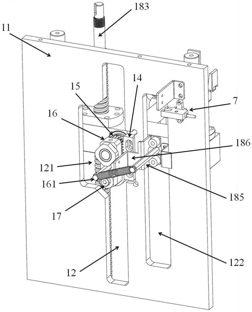
[0029] The cup cover claw rotation mechanism 1 includes a driving module, a rotating baffle plate 11 provided with a vertical guide groove 12, a cup cover claw connecting rod 13, and a rotati...
Embodiment 2
[0037] like figure 1 , Figure 4 , Figure 5 As shown, the automatic cup cover device also includes a cup grabbing mechanism 4, which is located at the lower station of the cup cover grabbing mechanism 2, and the cup grabbing mechanism 4 includes a left cup claw 41, a right cup claw 42, and a cup grab slide rail. 47. Cup grabbing gear 48, cup grabbing motor 49, when the left cup claw 41 and the right cup claw 42 are closed, the cup body is clamped, the left cup claw 41 is provided with a left claw drive plate 43, and the left claw drive plate 43 is provided with a left rack 45, the right cup claw 42 is provided with the right claw drive plate 44, the right claw drive plate 44 is provided with the right rack 46, the left claw drive plate 43, the right claw drive plate 44 are respectively slidably connected to the upper side and the upper side of the cup slide rail 47. Downside, the left rack 45, the cup gear 48, and the right rack 46 mesh successively, and the cup gear 48 is ...
Embodiment 3
[0041] like figure 1 As shown, the automatic cup cover device also includes a stop mechanism 8, and the stop mechanism 8 includes a stop lever 81, a stop slide rail 82, a stop motor 83, and a photosensitive element 7, and the photosensitive element 7 is arranged on the cup cover grip Take the lower station of the mechanism 2, the stop bar 81 is connected with the stop slide rail 82, the stop motor 83 drives the stop bar 81 to move, and when the light sensor 7 senses that there is a cup body 6, the stop motor 83 drives the stop bar 81 to move. The stop bar 81 stretches out and blocks the movement of the cup body 6 .
[0042] During the assembly line production process, when the photosensitive element 7 detects that there is a cup body 6 close to the automatic cup cover device, the power failure 83 machine drives the stop lever 81 to slide out along the stop slide rail 82 to stop the cup body 6 from moving. The position that moves forward on the assembly line, when the cup body...
PUM
 Abstract
Description
Claims
Application Information