Vacuum material suction conveying pump system and working method thereof

A technology of vacuum suction and conveying pumps, which is applied in the direction of conveyors, conveying bulk materials, transportation and packaging, etc. It can solve the problem that material suction and discharge cannot be carried out at the same time, achieve continuous and uninterrupted slag suction and slag discharge, and improve Efficiency of slag discharge, effect of solving the problem of sewage transportation

Inactive Publication Date: 2020-09-01
CHINA RAILWAY ENGINEERING EQUIPMENT GROUP CO LTD
View PDF7 Cites 5 Cited by
  • Summary
  • Abstract
  • Description
  • Claims
  • Application Information

AI Technical Summary

Problems solved by technology

[0004] In view of the deficiencies in the above-mentioned background technology, the present invention proposes a vacuum suction material delivery pump system and its working method, which solves the problem that the suction and discharge of the hollow material suction delivery pump system in the prior art cannot be carried out simultaneously

Method used


Image

  • Vacuum material suction conveying pump system and working method thereof

Examples


Embodiment 2

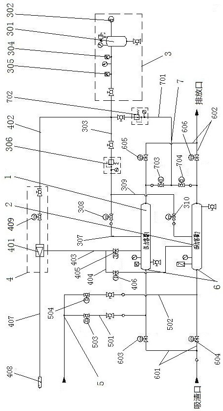
[0034] Embodiment 2, a vacuum suction and delivery pump system, the vacuum generating unit 4 includes a vacuum generator 401, the vacuum generator 401 uses a Laval nozzle vacuum generator, the Laval nozzle vacuum generator is used to provide a vacuum environment for the pressure vessel In turn, the material is pressed into the pressure vessel by atmospheric pressure. The vacuum generator 401 is connected to the positive pressure main line 303 through the positive pressure input pipeline 402. The positive pressure input pipeline 402 is provided with a 13th valve 409, which is used between the positive pressure pipeline and the vacuum generator. On-off of high-pressure gas. The vacuum generator 401 is connected to the first pressure vessel 1 through a first negative pressure sub-line 403, and the vacuum generator 401 is connected to the second pressure vessel 2 through a second negative pressure sub-line 404. The first negative pressure sub-line No. 10 valve 405 is provided on 4...

Embodiment 3

[0037] Embodiment 3 is a vacuum suction and delivery pump system. The suction and discharge unit 6 includes a suction pipe 601 and a discharge pipe 602. The suction pipe 601 is connected to the suction ports of the first pressure vessel 1 and the second pressure vessel 2, respectively, The discharge pipe 602 is respectively connected with the slag discharge ports of the first pressure vessel 1 and the second pressure vessel 2; the suction pipe 601 and the first pressure vessel 1 are provided with a No. 1 valve 603, which is used to control the first The on-off of the slag suction channel of the pressure vessel, a No. 2 valve 604 is provided between the suction pipe 601 and the second pressure vessel 2, and the No. 2 valve 604 is used to control the on-off of the slag suction channel of the second pressure vessel. A No. 3 valve 605 is provided between the discharge pipe 602 and the first pressure vessel 1. The No. 3 valve 605 is used to control the slag discharge of the first pre...

Embodiment 4

[0040] Embodiment 4: A pumping method of a vacuum suction and delivery pump system, including slag suction and slag discharge modes, suction pipe and discharge pipe backwash mode, pressurized pneumatic conveying mode, and improved mode.

[0041] The slag suction and discharge mode includes the following steps:

[0042] A1: When the air compressor is in working condition, firstly open the No. 13 valve, No. 10 valve and No. 1 valve to make the first pressure vessel vacuum so that the slag is sucked into the first pressure vessel;

[0043] A2: When the first pressure vessel is full of slag or the set time is reached, the No. 10 valve and the No. 1 valve are closed; the No. 7 valve, the No. 3 valve, the No. 9 valve, and the No. 2 valve are opened to allow the positive pressure air to enter The first pressure vessel thus realizes the slag discharge of the first pressure vessel, while the second pressure vessel forms a vacuum so that the slag is sucked into the second pressure vessel;

[00...


PUM


Abstract

The invention discloses a vacuum material suction conveying pump system and a working method thereof. The vacuum material suction conveying pump system solves the problem that in the prior art, a vacuum material suction conveying pump system cannot suck materials and discharge the materials at the same time. The vacuum material suction conveying pump system involves a first pressure container anda second pressure container arranged in parallel, wherein a positive pressure generation unit, a vacuum generation unit, an improvement unit and a slag suction and discharge unit are connected to thefirst pressure container and the second pressure container, the vacuum generation unit is connected with the positive pressure generation unit, and the improvement unit is connected with the slag suction and discharge unit. The vacuum material suction conveying pump system is ingenious in design, fluids carrying a large amount of particulate matter or the particulate matter and solid powder can beconveyed, and continuous and uninterrupted slag suction and slag discharge can be achieved so that the waste water conveying problem in tunnel construction can be better solved, and the vacuum material suction conveying pump system has high practicability and popularization value.

Description

Technical field [0001] The invention relates to the technical field of shield machine pneumatic conveying, in particular to a vacuum suction and conveying pump system and a working method thereof. Background technique [0002] At present, during the construction of the shield machine, although there is a relatively complete slag discharge system, sewage will still accumulate in the tunnel, and the sewage is often mixed with sand, gravel and soil; this requires strong sewage conveying equipment Due to the limited space in the tunnel, there are not many equipment to choose from. At present, the shield machine usually uses a pneumatic diaphragm pump to pump sewage. Although a filter device is installed at the inlet of the pneumatic diaphragm pump, the diaphragm pump The diaphragm is still often damaged by incoming particles. [0003] Based on the above reasons, construction units have begun to seek new equipment for the discharge of tunnel sewage. At present, some domestic tunnel con...

Claims


Application Information

Patent Timeline
Patent Type & Authority Applications(China)
IPC IPC(8): B65G53/24B65G53/52B65G53/58B65G53/66
CPCB65G53/24B65G53/52B65G53/58B65G53/66
Inventor 郭志勇俞培德姚晶李光周小磊赵云辉吴豪朱团辉冯超强赵石赵康峰李泽魁
Owner CHINA RAILWAY ENGINEERING EQUIPMENT GROUP CO LTD
Why Eureka
Try Eureka