Floating type feeding device for roller press

A feeding device, floating technology, applied in the field of roller press floating feeding device, to achieve the effect of increasing the bite effect and increasing the friction force

Inactive Publication Date: 2020-09-01
SINOSTEEL ANHUI TIANYUAN TECH
View PDF6 Cites 0 Cited by
  • Summary
  • Abstract
  • Description
  • Claims
  • Application Information

AI Technical Summary

Problems solved by technology

[0004] At present, the feeding system of the roller press on the market is relatively simple. Generally, it is directly transported from the silo to the middle of the two extrusion rollers of the roller press through the feeding pipeline. According to the output requirements of the roller press on site, there will be some The rod or plate inserted into the feeding pipe can be adjusted by adjusting the internal passing area of ​​the feeding pipe. At present, the manufacturers and scientific research institutions of the roller press have not conducted in-depth research on this.

Method used


Image

  • Floating type feeding device for roller press
  • Floating type feeding device for roller press
  • Floating type feeding device for roller press

Examples


Embodiment 1

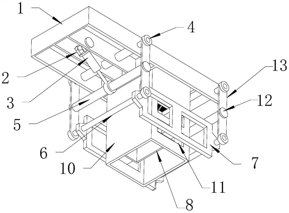
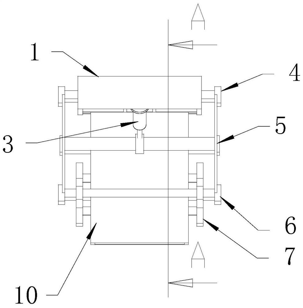
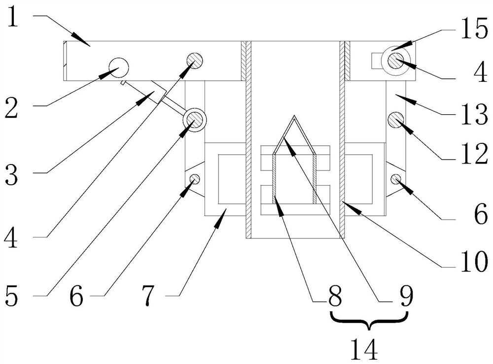
[0027] like Figure 1 to Figure 4 As shown, a floating feeding device for a roller press of the present invention includes a main frame 1 and a feeding channel 10 vertically arranged on the main frame 1. The section of the feeding channel 10 is a square or a rectangle, and the main frame On the frame 1, the two sides of the feeding channel 10 are respectively provided with first suspension pins 4, and the two ends of each suspension pin 4 are respectively connected with swing arms 13; the front and rear sides of the lower part of the feeding channel 10 are The wall is respectively provided with through holes 11, and the outside of each through hole 11 is provided with a swing frame 7, and the inside of the feeding channel 10 is also provided with a screening device 14, and the front and rear sides of the screening device 14 are respectively connected to two swinging frames. The frames 7 are connected and fixed; the two ends of one swing frame 7 are connected with the two ends ...

Embodiment 2

[0030] On the basis of embodiment 1, in order to facilitate the automatic control of the floating feeding device of the roller press, as Figure 1 to Figure 5As shown, the feeding device also includes a PLC controller 16 and a hydraulic station 17, wherein an angle sensor 15 is installed at the end of one of the first suspension pins 4, and the ejector device 3 and the hydraulic station 17 The hydraulic station 17 and the angle sensor 15 are respectively connected to the PLC controller 16 through lines. In this embodiment, the PLC controller 16 can be connected with the roller press control system, and according to the data of the roller press operation and the feedback data of the angle actuator 15, the PLC program instruction is transmitted to the hydraulic station 17, and the hydraulic station 17 is controlled to Hydraulic oil is pumped into the ejector device 3 to drive the extension and contraction of the ejector device 3, and then control the position of the screening de...


PUM

PropertyMeasurementUnit
Gapaaaaaaaaaa

Abstract

The invention discloses a floating type feeding device for a roller press. The floating type feeding device for the roller press comprises a main rack and a feeding channel, wherein two first suspension pins are arranged on the main rack, and the two ends of each suspension pin are movably connected with swing arms; through holes are formed in the front side wall and the rear side wall of the lower portion of the feeding channel, a swing frame is arranged on the outer side of each through hole, a screening device is further arranged inside the feeding channel, and the front side and the rear side of the screening device are connected with the two swing frames; the two ends of one swing frame are connected with the two ends of the other swing frame through second suspension pins, and the two ends of each second suspension pin are movably connected with the lower ends of the swing arms at the ends; an ejector rod connecting shaft is movably connected between the middles of the two swingarms on the same side of the main rack, and a stabilizing rod is connected between the middles of the two swing arms on the other side; and an ejector rod device is movably connected to the middle ofthe ejector rod connecting shaft. The floating type feeding device for the roller press has the advantages that the structural design is novel and reasonable, manufacturing is convenient, the problemof material feeding of the roller press is effectively solved, the effect is good, and the practicability is high.

Description

technical field [0001] The invention belongs to the technical field of material crushing equipment, and in particular relates to a floating feeding device for a roller press. Background technique [0002] The working principle of the roller press is to rely on two squeeze rollers to squeeze the passing material, causing the material to be crushed. This working principle requires that the material and the roller surface remain relatively stationary to improve the crushing effect. However, if the material and the roller surface move relative to each other, the material will move under the action of pressure and rub against each other, which will reduce the pressure on the material particles, and at the same time, a large amount of heat will be generated due to friction, which will negatively affect the stable operation of mechanical equipment. If the material slips, it will directly reduce the crushing effect of the roller press and directly affect the output of qualified prod...

Claims


Application Information

Patent Timeline
IPC IPC(8): B65G69/12B02C23/02
CPCB02C23/02B65G69/12
Inventor 马超韩呈宋晓刚徐海阳
Owner SINOSTEEL ANHUI TIANYUAN TECH
Why Eureka
Try Eureka