Sleeve mounting machine for building engineering

A technology of construction engineering and installation machine, which is applied in the direction of construction, building structure, and construction material processing, etc., which can solve the problems of low installation efficiency and physical exertion, and achieve the effect of labor-saving installation and improved mobile performance

Active Publication Date: 2020-09-01
马鞍山市神飞机械配件制造有限公司
View PDF5 Cites 0 Cited by
  • Summary
  • Abstract
  • Description
  • Claims
  • Application Information

AI Technical Summary

Problems solved by technology

[0003] At present, most of the installation of steel bar sleeves are manually operated, holding the installation wrench and the installation pliers, and two people need to cooperate to operate, which is very labor-intensive and the installation efficiency is low

Method used


Image

  • Sleeve mounting machine for building engineering
  • Sleeve mounting machine for building engineering
  • Sleeve mounting machine for building engineering

Examples


Embodiment 1

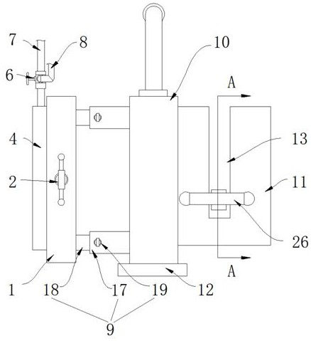
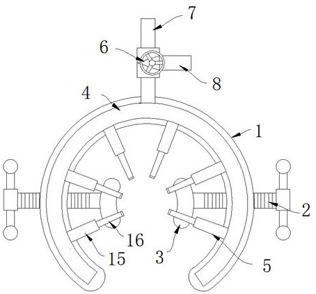
[0027] refer to Figure 1-5 , a sleeve installation machine for construction engineering, including a hydraulic power element and an actuator, the hydraulic power element provides a power source for the actuator, the actuator includes an outer arc ring 1, and the front and rear sides of the outer arc ring 1 are screwed with threads Clamping rod 2, one end of the threaded clamping rod 2 extending to the inside of the outer arc ring 1 is rotatably connected with an extrusion block 3, the left side of the outer arc ring 1 is fixedly connected with an arc-shaped oil pipe 4, and the inner arc surface of the arc-shaped oil pipe 4 A plurality of telescopic columns 5 are installed, and the telescopic columns 5 are composed of a bottom pipe 15 and a movable column 16 plugged in the bottom pipe 15, and the bottom pipe 15 communicates with the inside of the arc oil pipe 4.

[0028] The arc oil pipe 4 communicates with the output pipe 7 and the input pipe 8 of the hydraulic power element ...

Embodiment 2

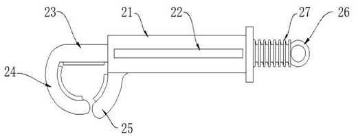
[0032] refer to Figure 6-7 The difference from Embodiment 1 is that the opposite surfaces of the fixed clamp hook 25 and the movable clamp hook 24 are provided with anti-slip rubber pads 35, and the hydraulic power components include a battery 29 fixedly installed on the upper surface of the cart 28, a hydraulic oil pump 30 and a storage battery. Oil tank 31, battery 29 are electrically connected with hydraulic oil pump 30, the output end of hydraulic oil pump 30 communicates with output pipe 7, the input end of hydraulic oil pump 30 communicates with oil storage tank 31, and the interior of input pipe 8 communicates with oil storage tank 31.

[0033] The surface of the output pipe 7 connected to the hydraulic oil pump 30 is provided with a control valve 32, the upper surface of the cart 28 is provided with a riser 33, the left side of the riser 33 is provided with a push handle, and the right side of the riser 33 is provided with a top plate 34, and The lower surface of the ...


PUM


Abstract

The invention discloses a sleeve mounting machine for building engineering. The sleeve mounting machine comprises a hydraulic power element and an executing element; the hydraulic power element provides a power source for the executing element; the executing element comprises an outer arc ring; threaded clamping rods are in threaded connection on the front and back sides of the surface of the outer arc ring; an extruding block is rotationally connected at one end, extending into the outer arc ring, of each threaded clamping rod; and an arc-shaped oil pipe is fixedly connected on the left sideof the outer arc ring. According to the sleeve mounting machine for building engineering, a hydraulic driving element is used for providing hydraulic oil for the inside of the arc-shaped oil pipe, multiple telescopic columns arranged circumferentially at equal intervals are driven to clamp a reinforcing steel bar or a reinforcing steel bar sleeve stably, and meanwhile, the shapes of an N-shaped frame, an N-shaped pipe and the outer arc ring in the mounting machine adopt N-shaped structures having lower openings, so that by the aid of the mounting machine, the reinforcing steel bar and the reinforcing steel bar sleeve can be fixed directly from the upper sides of the reinforcing steel bar and the reinforcing steel bar sleeve, lantern ring type mounting is not required to be adopted, and themounting machine has the effects that continuous operation is facilitated and the mounting machine can be separated from the reinforcing steel bar sleeve conveniently.

Description

technical field [0001] The invention relates to the technical field of construction engineering, in particular to a construction engineering sleeve installation machine. Background technique [0002] The steel bar sleeve, also known as the steel bar joint, is a connecting piece used to connect steel bars and has an internal thread corresponding to the wire thread. The construction process is as follows: the end of the steel bar is processed into a straight thread by rolling process, and the two steel bars are connected to each other with the corresponding connecting sleeve to complete the connection of the two steel bars. [0003] At present, most of the installation of steel bar sleeves is manually operated, with a hand-held installation wrench and installation pliers, and two people need to cooperate to operate, which is very labor-intensive and the installation efficiency is low. [0004] Therefore, we propose a construction engineering sleeve installation machine. Con...

Claims


Application Information

Patent Timeline
IPC IPC(8): E04G21/12
CPCE04G21/122
Inventor 汤本银
Owner 马鞍山市神飞机械配件制造有限公司
Why Eureka
Try Eureka