Check patentability & draft patents in minutes with Patsnap Eureka AI!

Improved rotary drilling machine coring drilling tool

A rotary excavator, an improved technology, applied to drilling tools, rotary drilling rigs, earthwork drilling and mining, etc., can solve problems such as shedding and drilling tool wear, and achieve the effect of effective shedding and reducing sloshing loss

Active Publication Date: 2020-09-01
湖北旭腾建设工程有限公司
View PDF9 Cites 0 Cited by
  • Summary
  • Abstract
  • Description
  • Claims
  • Application Information

AI Technical Summary

Problems solved by technology

[0004] Aiming at the deficiencies in the prior art, the object of the present invention is to provide an improved rotary excavator rock drilling tool to solve the problem in the prior art that when the rotary excavator is used to remove rocks, the first contact with the rock and soil is the extraction tool. For rock drilling tools, after the rock drilling tool reaches a certain depth inside the rock and soil, due to the inconsistency of the rock and soil structure, when the rock soil with high humidity is taken, the rock soil will be squeezed under the action of extrusion force. Under the converging extrusion inside the drill tool, and in the process of shaking and falling off by the equipment, it is difficult to completely fall off from the inside of the drill tool due to the cohesion of the rock and soil, which in turn leads to the need for continuous drilling. Under the double influence of the continuous vibration of the drilling tool and the rock extraction while the inside of the drilling tool still contains rock and soil, the drilling tool will be more severely worn and the rock soil will be placed in a compact state. internal defects

Method used


Image

  • Improved rotary drilling machine coring drilling tool
  • Improved rotary drilling machine coring drilling tool
  • Improved rotary drilling machine coring drilling tool

Examples


Embodiment

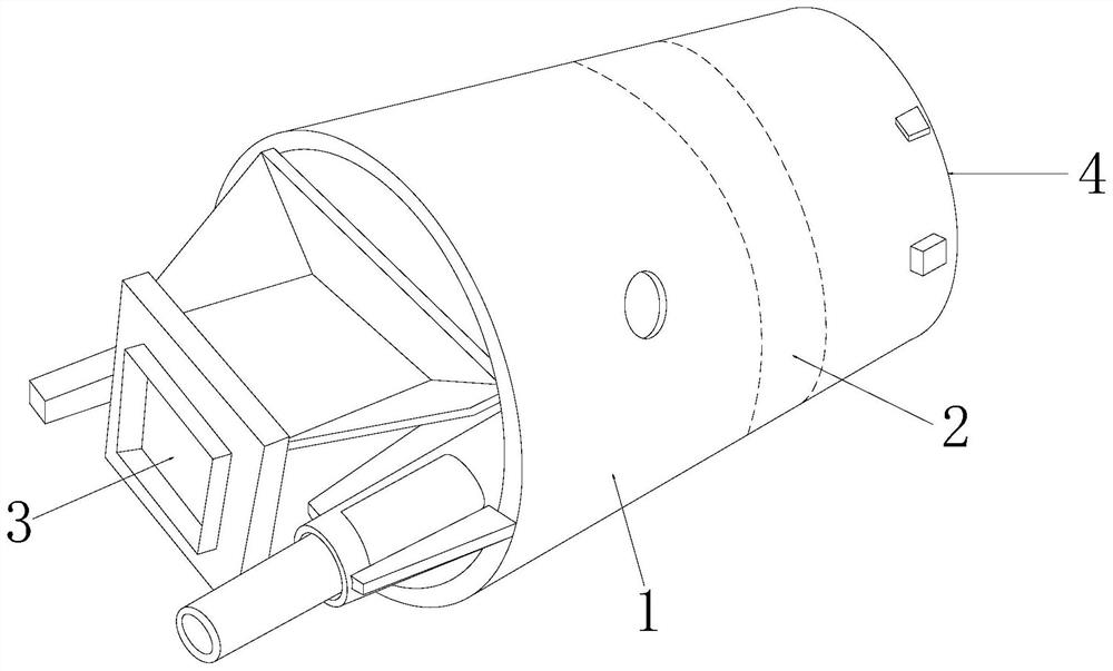
[0029] Such as Figure 1-Figure 6 As shown, the present invention provides a technical scheme of an improved rotary excavator rock drilling tool:

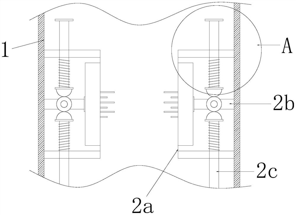
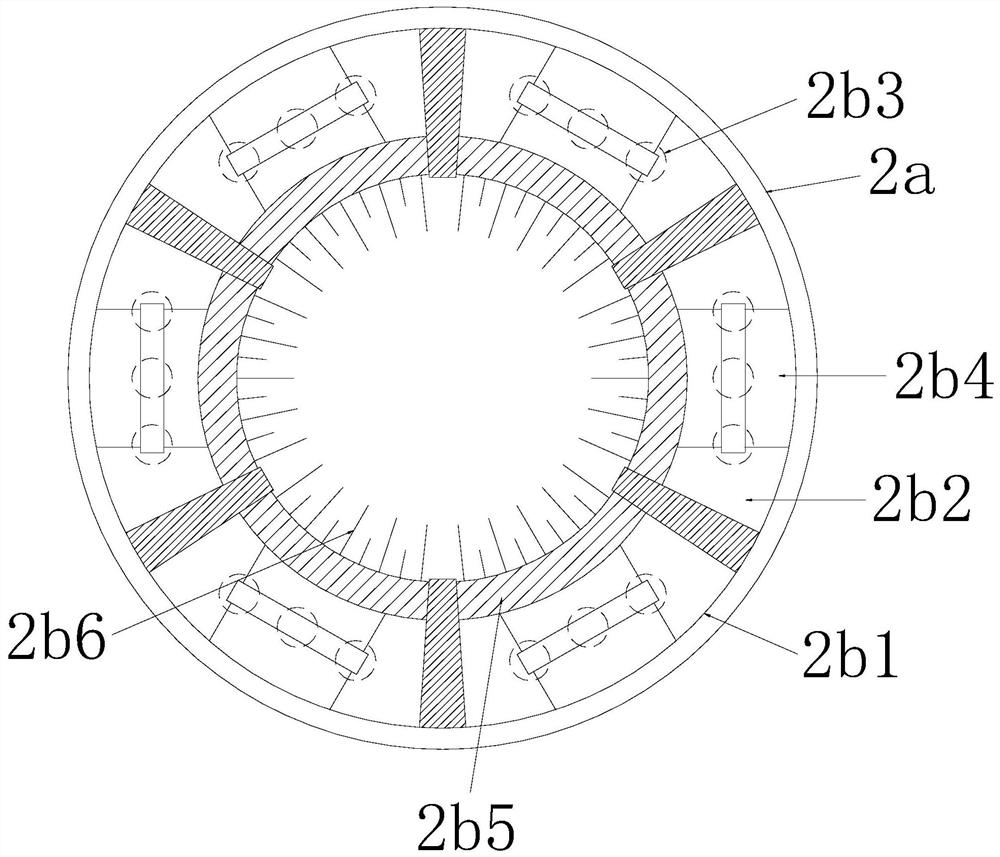
[0030] Such as Figure 1-Figure 2 As shown, an improved rock-taking drilling tool for rotary excavator has a structure including a drill barrel 1, an inner and outer breaking device 2, a fastening sleeve 3, and a tooth plate 4. The inner and outer breaking devices 2 are arranged on the drill The middle part of the inner wall of the tool barrel 1 is connected by electric welding. The fastening sleeve 3 is arranged on the upper end of the drill barrel 1 and connected vertically by electric welding. The tooth digging plate 4 is arranged on the lower surface of the drill barrel 1 and connected by electric welding. , the internal and external breaking device 2 includes a ring frame 2a, a sliding breaking mechanism 2b, and a pounding structure 2c, the sliding breaking mechanism 2b is arranged inside the ring frame 2a and connected by el...


PUM


Abstract

The invention discloses an improved rotary drilling machine coring drilling tool. The tool structurally comprises a drilling tool barrel, an inner and outer breaking device, a buckling sleeve and a drilling tooth plate. The tool has the beneficial effects that a sliding breaking mechanism and a tamping structure cooperate with each other, while realization of up-and-down shaking of excavated soilon the whole equipment is facilitated, under a track action of a loosening shaft moving back and forth with a push plate, internal outward pulling, hooking, removing and loosening of sludge, and external inward extrusion falling-off treatment are realized, therefore, it can guarantee that the excavated soil can effectively fall off in a large area mode under the action of overall shaking of the equipment, so that shaking consumption occurring during soil shaking by the drilling tool is reduced, a power source can be provided for the sliding breaking mechanism under the action of the tamping structure, meanwhile, the excavated soil is subjected to tamping and breaking matching, and under the interaction of the up-down back-and-forth thrust and grabbing force, loosened soil can be actively and passively slide off and fall off.

Description

technical field [0001] The invention relates to the field of construction equipment, more precisely, it is an improved rock-taking drilling tool for a rotary excavator. Background technique [0002] Before the pile foundation is buried in the construction site, it is necessary to use a rotary excavator to drill holes into the ground to ensure the effective depth and safety of the pile foundation. [0003] When using a rotary excavator to remove rocks, since the first contact with the rock and soil is the rock drilling tool, after the rock drilling tool penetrates to a certain depth inside the rock and soil, due to the inconsistent structure of the rock and soil, the When the rock soil with high humidity is used, the rock soil will be squeezed together inside the drilling tool under the action of the extrusion force, and in the process of shaking and falling off by the equipment, due to the cohesion of the rock and soil It is more difficult to fall off from the inside of the...

Claims


Application Information

Patent Timeline
Patent Type & Authority Applications(China)
IPC IPC(8): E21B12/06E21B3/02
CPCE21B3/02E21B12/06
Inventor 辛秋娥
Owner 湖北旭腾建设工程有限公司
Features
  • R&D
  • Intellectual Property
  • Life Sciences
  • Materials
  • Tech Scout
  • Unparalleled Data Quality
  • Higher Quality Content
  • 60% Fewer Hallucinations
Learn More