Engine braking method and device and vehicle

An engine braking, engine technology, applied in the direction of engine control, machine/engine, mechanical equipment, etc., can solve the problems of insufficient power, distraction of the driver, and inconvenient engine braking control methods.

Pending Publication Date: 2020-09-01
WEICHAI POWER CO LTD
View PDF3 Cites 2 Cited by
  • Summary
  • Abstract
  • Description
  • Claims
  • Application Information

AI Technical Summary

Problems solved by technology

The engine brake needs to be manually and automatically turned on when the driver has a braking demand, and the engine brake needs to be manually and automatically turned off when there is no need for brak...

Method used


Image

  • Engine braking method and device and vehicle
  • Engine braking method and device and vehicle
  • Engine braking method and device and vehicle

Examples


Embodiment 1

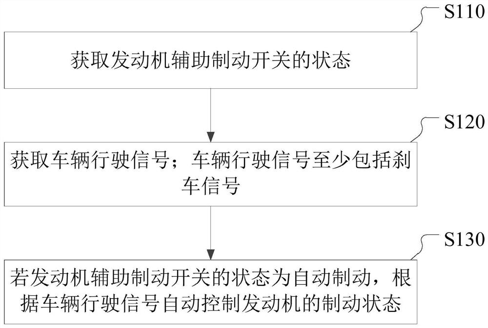
[0033] An embodiment of the present invention provides an engine braking method, figure 1 It is a flow chart of an engine braking method provided in Embodiment 1 of the present invention, refer to figure 1 , methods include:

[0034] S110. Obtain the state of the engine auxiliary brake switch.

[0035] Specifically, the engine braking method provided by the embodiment of the present invention obtains the state of the engine auxiliary brake switch through an electronic control unit (Electronic Control Unit, ECU). The engine auxiliary brake switch includes multiple gear positions, and each gear position corresponds to the state of the brake switch one by one. In the embodiment of the present invention, the engine brake gear is automatically turned on and off, and the state of the corresponding brake switch is automatic braking, that is, the ECU can automatically judge whether it is necessary to trigger the brake or exit the brake according to the vehicle driving signal, so as ...

Embodiment 2

[0042] The embodiment of the present invention provides an engine braking method. On the basis of the first embodiment above, the embodiment of the present invention supplements and refines the engine braking method.

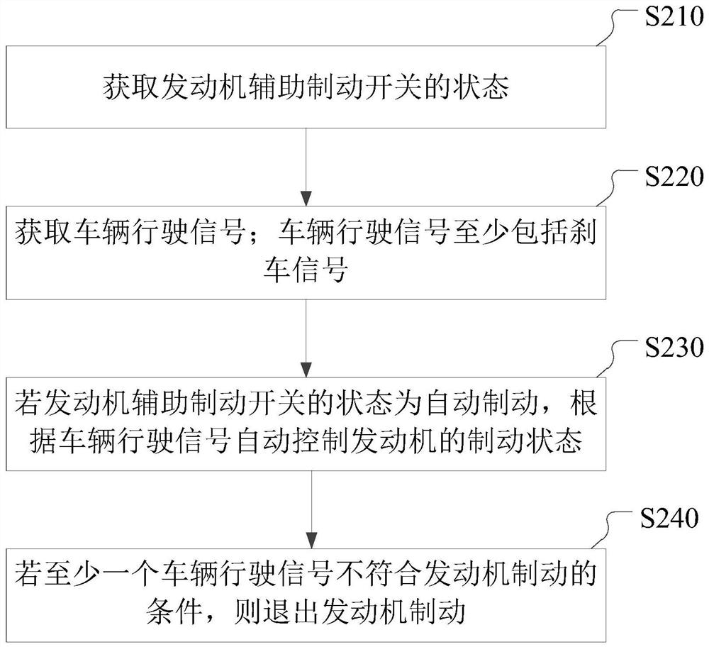
[0043] figure 2 It is a flow chart of an engine braking method provided in Embodiment 2 of the present invention, refer to figure 2 , methods include:

[0044] S210. Obtain the state of the engine auxiliary brake switch.

[0045] Optionally, the state of the engine auxiliary brake switch also includes manual braking and manual release of the brake, and correspondingly, the engine auxiliary brake switch also includes an engine brake switch closed position and an engine brake switch open position. When the engine auxiliary brake switch is at the closed position of the engine brake switch, the state of the engine auxiliary brake switch is manual braking; when the engine auxiliary brake switch is at the engine brake switch off position, the state of the engine a...

Embodiment 3

[0065] An embodiment of the present invention provides an engine braking device, Figure 4 It is a structural block diagram of an engine braking device provided in Embodiment 3 of the present invention, refer to Figure 4 , the device consists of:

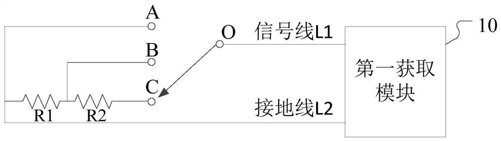
[0066] The first obtaining module 10 is used to obtain the state of the engine auxiliary brake switch;

[0067] The second acquiring module 20 is configured to acquire vehicle running signals; the vehicle running signals at least include braking signals;

[0068] The control module 30 is configured to automatically control the braking state of the engine according to the vehicle running signal if the state of the engine auxiliary braking switch is automatic braking.

[0069] Specifically, the engine braking device includes a first acquisition module 10 , a second acquisition module 20 and a control module 30 . The first obtaining module 10 is used to obtain the state of the engine auxiliary brake switch, and obtaining the state ...


PUM


Abstract

The embodiment of the invention discloses an engine braking method and device and a vehicle. The engine braking method comprises the steps that the state of an engine auxiliary braking switch is obtained; a vehicle driving signal is obtained, wherein the vehicle driving signal at least comprises a brake signal; and if the state of the engine auxiliary braking switch is automatic braking, the braking state of the engine is automatically controlled according to the vehicle driving signal. According to the technical scheme provided by the engine braking method and device and the vehicle, controlover engine braking is simplified, normal work of the vehicle is guaranteed, distraction of a driver is avoided, and safety guarantee is improved.

Description

technical field [0001] Embodiments of the present invention relate to the technical field of electronically controlled engines, in particular to an engine braking method, device and vehicle. Background technique [0002] Engine braking, also known as engine retarder, is an auxiliary braking system that can effectively reduce the phenomenon of overheating of brake pads and brake failure when going down a long slope; engine braking includes exhaust braking and in-cylinder compression release brake. [0003] At present, the engine auxiliary brake switch includes an engine brake switch open gear and an engine brake switch close gear. The engine brake needs to be manually and automatically turned on when the driver has a braking demand, and the engine brake needs to be manually and automatically turned off when there is no need for braking; the engine braking control method is inconvenient and will distract the driver's attention, and if you forget Closing off in time can lead ...

Claims


Application Information

Patent Timeline
IPC IPC(8): F02D9/06F02D13/04F02D29/02
CPCF02D9/06F02D13/04F02D29/02F02D2200/60F02D2200/501F02D2200/50
Inventor 赵崇男朱兴军殷月祥马靖宁
Owner WEICHAI POWER CO LTD
Why Eureka
Try Eureka