

Fracturing manifold quick connecting device
A fracturing pipe and oil supply device technology, applied in the field of fracturing, can solve the problems of difficult assembly, poor adaptability, reverse flow of fracturing fluid, etc., so as to reduce the difficulty of manual operation, reduce maintenance costs, and increase service life. Effect
- Summary
- Abstract
- Description
- Claims
- Application Information
AI Technical Summary
Problems solved by technology
Method used
Image

Examples
Embodiment Construction
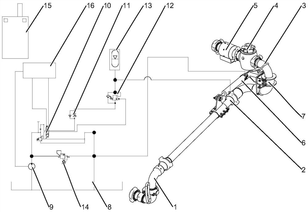
[0014] like figure 1 As shown, a fracturing manifold quick-connecting device includes a first swivel elbow 1, a straight pipe 2, a second swivel elbow 3, an oil cylinder 6, a support 7, a plug valve 4, a check valve 5, and a hydraulic system , the control unit, the first swivel elbow 1, the straight pipe 2, the second swivel elbow 3, the plug valve 4 and the check valve 5 are sequentially connected, and the fracturing fluid is sequentially passed through the first swivel elbow 1 by the fracturing equipment , straight pipe 2, second swivel elbow 3, plug valve 4 and check valve 5 are delivered to the manifold skid. The support 7 is fixedly connected to the second elbow 3, specifically, the second elbow 3 includes a first elbow and a second elbow and the first elbow and the second elbow are rotatably connected, The first elbow is also connected to the plug valve 4, the second elbow is also connected to the straight pipe 2, and the support 7 is fixedly connected to the first elbo...
PUM
 Abstract
Description
Claims
Application Information