Combined oil thrower

An oil thrower and combined technology, which is applied in combustion methods, combustion chambers, combustion equipment, etc., can solve the problems of uneven oil throwing, small fuel atomization cone angle, and improvement of crushing and atomization effects, etc., to achieve Better atomization effect and better outlet temperature field distribution

Active Publication Date: 2020-09-01
NORTHWESTERN POLYTECHNICAL UNIV
View PDF5 Cites 3 Cited by
  • Summary
  • Abstract
  • Description
  • Claims
  • Application Information

AI Technical Summary

Problems solved by technology

[0003] The disadvantage of the existing oil throwing plate nozzle is that the fuel atomization cone angle is not large, the amount of oil thrown by each nozzle is not uniform enough, and the effect of crushing and atomization needs to be improved

Method used


Image

  • Combined oil thrower
  • Combined oil thrower
  • Combined oil thrower

Examples


Embodiment Construction

[0020] The present invention will be further described now in conjunction with accompanying drawing:

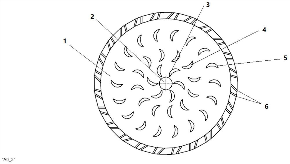
[0021] combine figure 1 , the invention provides a combined oil flinger.

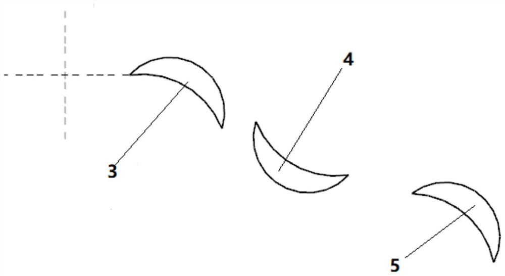
[0022] Specific process: liquid fuel flows into the cavity of the oil thrower through the inlet 2 of the oil delivery pipe, and passes through the equalizer 3, which is the first-level spoiler column, to ensure that the amount of fuel injected by each oil hole is equal and the temperature field at the outlet of the combustion chamber is evenly distributed. Afterwards, it flows through the secondary spoiler column 4 and the third-stage spoiler column 5 in sequence. Due to the high-speed rotation of the main disc 1 of the oil thrower, the fuel in the cavity is expanded into a thin film. When the thin film impacts the spoiler strut device, the flow state of the liquid working medium is changed many times, colliding, bifurcating, changing direction, tearing, the shape of the thin liquid film changes more ...


PUM


Abstract

The invention provides a combined oil thrower. An engine using an oil thrower fuel nozzle is high in combustion efficiency, has a cooling effect on a shaft rotating at high speed, and also preheats fuels, so that atomization, evaporation and organization combustion are facilitated. A turbulent flow support column is arranged in a cavity, and an interactive nozzle is adopted, so that purposes of improving fuel atomization level and improving outlet temperature field distribution are achieved. A liquid working medium is collided, branched and turned by the turbulent flow support column device for multiple times, and a thin liquid film is torn and broken more thoroughly; and fuels thrown at high speed are collided at the nozzle, so that the final atomization effect is better.

Description

technical field [0001] The invention belongs to the technical field of combustion chambers of gas turbines, and in particular relates to a combined oil throwing pan. Background technique [0002] The oil flinger is a special form of fuel nozzle, which is mainly used for the oil supply device of the baffle annular combustion chamber with high speed and small flow. The most famous oil thrower is the oil thrower system of Turbomeca, France, which is also used in the combustion chamber of WP11 engine. The fuel is supplied through the center of the hollow compressor-turbine shaft, and there are several small holes on the periphery of the oil throwing pan. In the head, due to the high-speed rotation of the shaft, the fuel is subjected to centrifugal force, interacts with the air, and breaks up the atomization. The engine using the oil flinger fuel nozzle has high combustion efficiency, and has a cooling effect on the high-speed rotating shaft, and also preheats the fuel, which i...

Claims


Application Information

Patent Timeline
Patent Type & Authority Applications(China)
IPC IPC(8): F23R3/28F23R3/30F23R3/38
CPCF23R3/286F23R3/30F23R3/38
Inventor 张群杨福正李小龙胡凡程祥旺刘强
Owner NORTHWESTERN POLYTECHNICAL UNIV
Why Eureka
Try Eureka