
Vehicle data flow test system and method

The technology of a test system and test method is applied in the field of test system of vehicle data flow, which can solve the problem of high test cost and achieve the effect of simple test and low test cost

Active Publication Date: 2020-09-01
纬湃科技投资(中国)有限公司
View PDF10 Cites 0 Cited by
  • Summary
  • Abstract
  • Description
  • Claims
  • Application Information

AI Technical Summary

Problems solved by technology

Higher testing costs due to the need for the driver to assist the tester to complete the test

Method used


Image

  • Vehicle data flow test system and method
  • Vehicle data flow test system and method
  • Vehicle data flow test system and method

Examples


Embodiment Construction

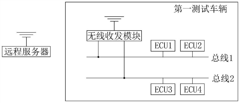
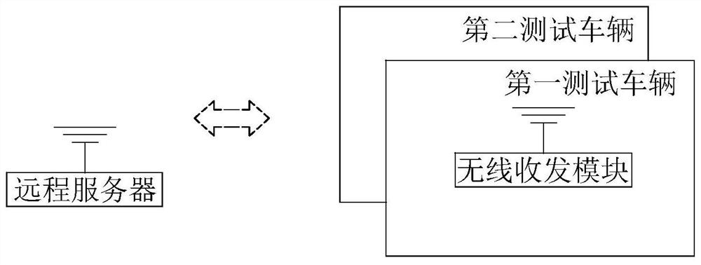
[0023] See figure 2 As shown, the present invention is a vehicle data flow testing system, which includes a remote server and a first test vehicle that is communicatively connected with the remote server. The first test vehicle includes a bus, an ECU (Electronic Control Unit, electronic control unit) connected to the bus, and a wireless transceiver module. The remote server communicates with the first test vehicle through communication with the wireless transceiver module. In this embodiment, the bus includes a bus 1 and a bus 2, and the bus 1 is connected with ECU1 and ECU2, and the bus 2 is connected with ECU3 and ECU4. The wireless transceiver module is signally connected with bus 1 and bus 2. Although this embodiment is described in this way, there is one bus or more buses, and one ECU or multiple ECUs on each bus belong to the protection scope of this patent.

[0024] The wireless transceiver module is connected to the remote server, and the wireless transceiver module is...


PUM


Abstract

The invention provides a vehicle data flow test system and method. The test system comprises a remote server and a first test vehicle in communication connection with the remote server. The first testvehicle comprises a bus, an ECU connected with the bus and a wireless transceiver module in signal connection with the ECU. The remote server communicates with the ECU through communication with thewireless transceiver module; the remote server is provided with a reading module and a monitoring module, the remote server reads data flow information of a signal to be tested through the reading module and monitors message information on a current bus through the monitoring module, and if the data flow information and the message information are consistent or within a set error range, the data flow test of the signal to be tested in the state is passed. The test system and method are simple in test and low in cost.

Description

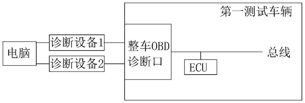
Technical field [0001] The invention relates to a test system and method for vehicle data flow. Background technique [0002] See figure 1 As shown, the computer reads the data flow information of the signal to be tested through the diagnostic device 1, and at the same time monitors the message information on the current bus through the diagnostic device 2. Compare the data flow information of the signal to be tested with the message information of the signal on the bus. If the physical values ​​of the two are the same or within the error range, the signal data flow test for the signal value passes. The diagnostic equipment 1 and the diagnostic equipment 2 are connected to the computer in a wired manner, and are connected to the OBD diagnostic port of the test vehicle in a wired manner to realize the communication connection with the test vehicle. [0003] In general, in order to ensure the stability of the signal reading, the state of the vehicle needs to be kept in a stable work...

Claims


Application Information

Patent Timeline
IPC IPC(8): G05B23/02
CPCG05B23/0213
Inventor 吴远波
Owner 纬湃科技投资(中国)有限公司
Learn More