Multi-frequency slot antenna, terminal equipment and antenna design method

A technology for slot antennas and terminal equipment, applied in slot antennas, antenna equipment with additional functions, antennas, etc., can solve the problems of limited design space, small size, and difficulty in satisfying antenna functions for slot antennas, and achieve rich equipment functions, Effects of improving antenna performance and increasing effective electrical length

Pending Publication Date: 2020-09-01
ANHUI HUAMI INFORMATION TECH CO LTD
View PDF0 Cites 5 Cited by
  • Summary
  • Abstract
  • Description
  • Claims
  • Application Information

AI Technical Summary

Problems solved by technology

For wearable devices, their volume is often small, and the design space of the slot antenna is limited, so it is difficult to meet the antenna functions of more frequency bands

Method used


Image

  • Multi-frequency slot antenna, terminal equipment and antenna design method
  • Multi-frequency slot antenna, terminal equipment and antenna design method
  • Multi-frequency slot antenna, terminal equipment and antenna design method

Examples


Embodiment Construction

[0054] The technical solutions of the present disclosure will be clearly and completely described below in conjunction with the accompanying drawings. Apparently, the described implementations are part of the implementations of the present disclosure, but not all of them. Based on the implementation manners in the present disclosure, all other implementation manners obtained by persons of ordinary skill in the art without creative efforts shall fall within the protection scope of the present disclosure. In addition, the technical features involved in different embodiments of the present disclosure described below may be combined with each other as long as they do not constitute a conflict with each other.

[0055] The slot antenna refers to the antenna formed by opening a slot on the conductor surface. The typical slot shape is a long strip, and the feed across the slot is used as the excitation source of the antenna. The working principle of the slot antenna is similar to tha...


PUM


Abstract

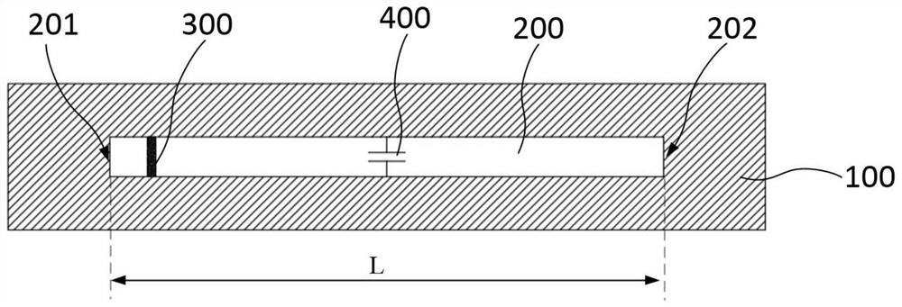
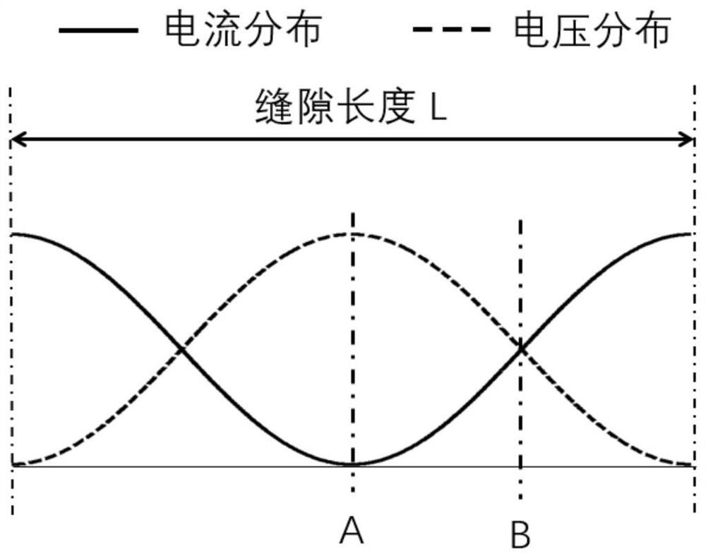
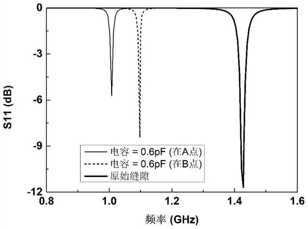
The invention relates to the technical field of electronic equipment, and particularly provides a multi-frequency slot antenna, terminal equipment and an antenna design method. The antenna is appliedto the terminal equipment, the terminal equipment comprises a metal shell, the antenna comprises: a gap formed in the metal shell, whereinthe gap is provided with a first end and a second end which are opposite in the length direction; afeed terminal which stretches across the gap and is located between the first end and the second end; and afirst capacitor which is arranged in the gap, whereinthetwo poles of the first capacitor are correspondingly connected to the two sides of the gap in the width direction respectively,the working frequency of the antenna comprises a multi-order resonant frequency, and the first capacitor is located at a position where the voltage values of the multi-order resonant frequency are not zero in the length direction. According to the antenna disclosed by theinvention, the effective electrical length of the slot antenna can be increased, and different resonant frequencies of the slot antenna can be adjusted according to the capacitance value of the position of the first capacitor, so that the adjusted resonant frequency falls within a required frequency range.

Description

technical field [0001] The present disclosure relates to the technical field of electronic equipment, and in particular to a multi-frequency slot antenna, a terminal device, and an antenna design method. Background technique [0002] With the development of electronic devices, smart wearable devices can achieve more and more functions. Taking a smart watch as an example, it has functions such as sports assistance, satellite positioning, wireless connection, and calling, and these functions need to be realized by the built-in antenna of the watch. [0003] In order to pursue the beauty and texture of the appearance of the device, more and more smart wearable devices use an all-metal shell, and at the same time use a slot antenna to realize the antenna function. The slot antenna refers to opening a strip-shaped slot on the metal shell, and radiating electromagnetic waves outward through the feed across the slot. In order to meet the requirements of the operating frequency of...

Claims


Application Information

Patent Timeline
Patent Type & Authority Applications(China)
IPC IPC(8): H01Q1/44H01Q1/36H01Q1/50H01Q5/10H01Q5/321H01Q5/50H01Q13/10H01Q1/22H01Q1/27G04R60/06
CPCG04R60/06H01Q1/22H01Q1/273H01Q1/36H01Q1/44H01Q1/50H01Q13/10H01Q5/10H01Q5/321H01Q5/50
Inventor 赵安平
Owner ANHUI HUAMI INFORMATION TECH CO LTD
Why Eureka
Try Eureka