High-low voltage switch cabinet with wireless temperature measurement assembly

A technology of wireless temperature measurement components and high and low voltage switches, which is applied in the field of high and low voltage switch cabinets, can solve the problems of electrical short circuit, no temperature sensor, debris entering, etc., to prevent electrical short circuit and ensure normal operation

Pending Publication Date: 2020-09-01
HUAINAN WANTAI RONGBO LIGHTING TECH
View PDF1 Cites 2 Cited by
  • Summary
  • Abstract
  • Description
  • Claims
  • Application Information

AI Technical Summary

Problems solved by technology

[0005] The purpose of the present invention is to provide a high and low voltage switchgear with wireless temperature measuring components to solve the problem that the existing high and low voltage switchgear does not have a temperature sensor and cannot transmit the temperature information inside the electrical compartment to the workers. To control the alarm light, workers cannot observe the flickering of the alarm light through the glass window, and cannot cool down in time; the existing high and low voltage switchgear does not have a temperature sensor, does not have an isolation door structure, and cannot filter debris in the air , sundries are easy to enter the interior of the electrical appliance compartment, affecting the normal operation of the electrical appliances. In rainy days, the ventilation window cannot be closed, and the rainwater enters the interior of the box, which is prone to short circuit of the electrical appliances; the existing high and low voltage switchgear does not have a temperature sensor. The air cannot be discharged from the air outlet hole at the bottom of the beam, and the heat inside the electrical compartment can be taken away, which cannot guarantee the normal operation of the electrical appliances

Method used


Image

  • High-low voltage switch cabinet with wireless temperature measurement assembly
  • High-low voltage switch cabinet with wireless temperature measurement assembly
  • High-low voltage switch cabinet with wireless temperature measurement assembly

Examples


Embodiment Construction

[0029] The technical solutions of the present invention will be clearly and completely described below in conjunction with the embodiments. Apparently, the described embodiments are only some of the embodiments of the present invention, not all of them. Based on the embodiments of the present invention, all other embodiments obtained by persons of ordinary skill in the art without creative efforts fall within the protection scope of the present invention.

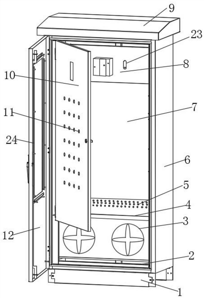
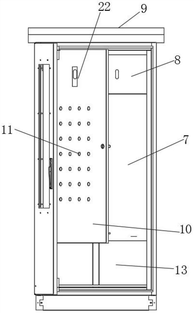
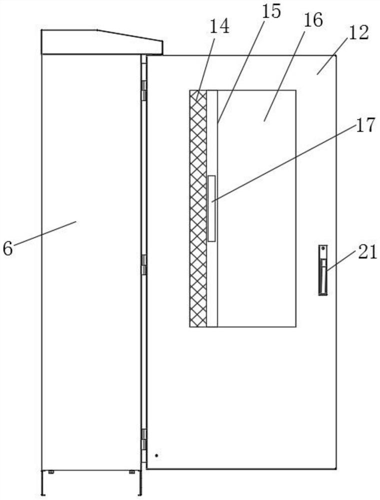
[0030] Such as Figure 1-5As shown, a high and low voltage switchgear with a wireless temperature measurement component includes a box body 6 and a cover plate 9, and the two sides of the bottom of the box body 6 are respectively provided with pads 1, and the two pads 1 are parallel to each other. The inside of the box body 6 is provided with an exhaust bin 13 near the bottom, an electrical appliance bin 7 is arranged above the exhaust bin 13, a driving bin 8 is arranged on the top of the electrical bin 7, and a Base plate...


PUM


Abstract

The invention discloses a high-low voltage switch cabinet with a wireless temperature measurement assembly. The device comprises a box body and a cover plate, and cushion blocks are arranged on the two sides of the bottom of the box body correspondingly. The two cushion blocks are parallel to each other; an exhaust bin is arranged in the box body and close to the bottom; an electric appliance binis arranged above the exhaust bin; a driving bin is arranged at the top of the electric appliance bin; a bottom plate is arranged between the exhaust bin and the electric appliance bin; a fan is arranged in the exhaust bin; a plurality of exhaust holes are formed in one side of the structure of the bottom plate; two cross beams are arranged at the bottom of the exhaust bin; two crossbeams are parallel to each other, after air enters the electric appliance cabin, the air enters the other side of the partition plate through the through holes in the partition plate to cool the electric applianceelements on the two side walls of the partition plate, then enters the exhaust bin through the exhaust holes in the bottom plate and is exhausted from the air outlet holes in the bottom of the cross beam through the fan, heat in the electric appliance bin is taken away, the electric appliance is cooled, and normal work of the electric appliance is guaranteed.

Description

technical field [0001] The invention relates to the field of switch cabinet equipment, in particular to a high and low voltage switch cabinet with a wireless temperature measuring component. Background technique [0002] As the name suggests, the high and low voltage switchgear is a device for connecting high-voltage or low-voltage cables. Generally, power supply bureaus and substations use high-voltage cabinets, which are then stepped down by transformers to low-voltage cabinets, and then to various power distribution boxes. It is nothing more than an electrical device that assembles some protective devices such as switch circuit breakers into one. At present, high and low temperature switch cabinets are prone to overheating and circuit burnout. [0003] The existing high-voltage and low-voltage switchgear does not have a temperature sensor, which cannot transmit the temperature information inside the electrical compartment to the workers, and does not have a control alarm...

Claims


Application Information

Patent Timeline
IPC IPC(8): H02B1/30H02B1/56H02B1/28G01K1/02G01K1/024
CPCH02B1/30H02B1/565H02B1/28G01K1/02
Inventor 李建书陈静王龙陈大伟陈浩苏龙
Owner HUAINAN WANTAI RONGBO LIGHTING TECH
Why Eureka
Try Eureka