Image imaging jitter compensation method, system and device

An image imaging and compensation method technology, which is applied in the field of image processing, can solve problems such as blurred video images, inability to effectively eliminate or slow down front-end equipment, and inability to balance image quality and eliminate screen shakes, etc.

Active Publication Date: 2020-09-01
FORYOU GENERAL ELECTRONICS
View PDF4 Cites 4 Cited by
  • Summary
  • Abstract
  • Description
  • Claims
  • Application Information

AI Technical Summary

Problems solved by technology

[0006] The present invention provides an image imaging shake compensation method, system and equipment, which solves the problem that the existing camera electronic anti-shake image processing technology cannot ef...

Method used


Image

  • Image imaging jitter compensation method, system and device
  • Image imaging jitter compensation method, system and device
  • Image imaging jitter compensation method, system and device

Examples


Embodiment 1

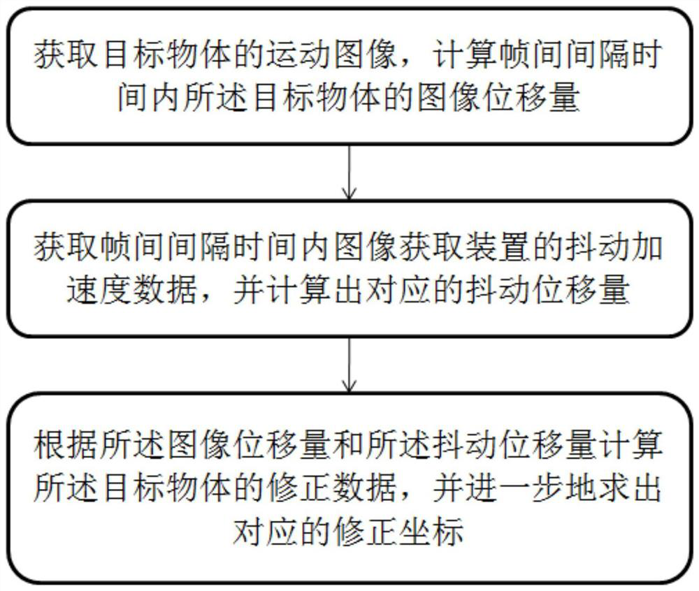
[0054] An image imaging shake compensation method provided by an embodiment of the present invention, such as Figure 1 ~ Figure 3 As shown, in this embodiment, including:

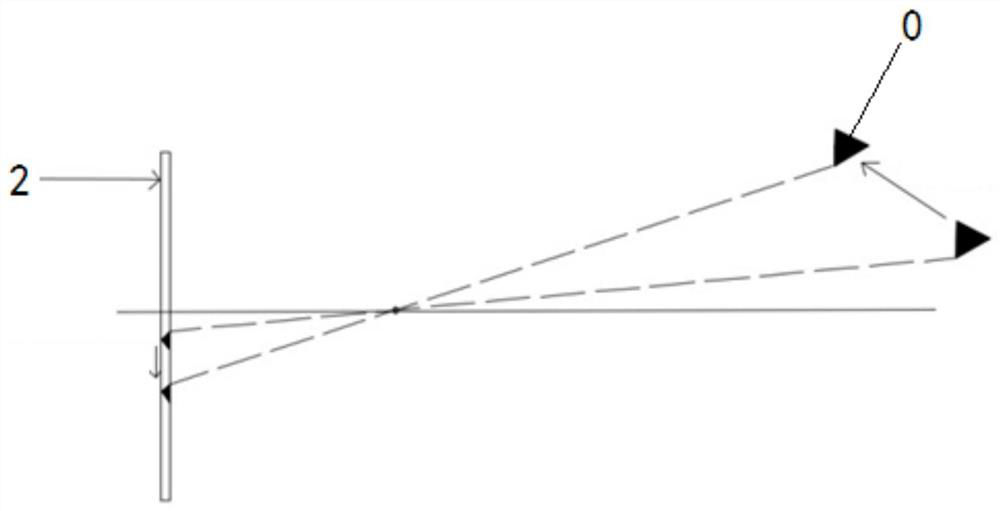
[0055] Acquire the moving image of the target object 0, and calculate the inter-frame interval time T C The image displacement of the target object 0 in ;

[0056] Get the inter-frame interval time T C The vibration acceleration data of the internal image acquisition device 2, and calculate the corresponding vibration displacement;

[0057] The correction data of the target object 0 is calculated according to the image displacement amount and the shaking displacement amount, and the corresponding correction coordinates are further obtained.

[0058] Preferably, it is assumed that the acquisition frequency of the image acquisition device 2 is F1, the output frequency of the sensor module 3 is F2, and the F2 is far greater than F1 (more than 10 times, such as 1KHz); The sampling rate K is the quotient of...

Embodiment 2

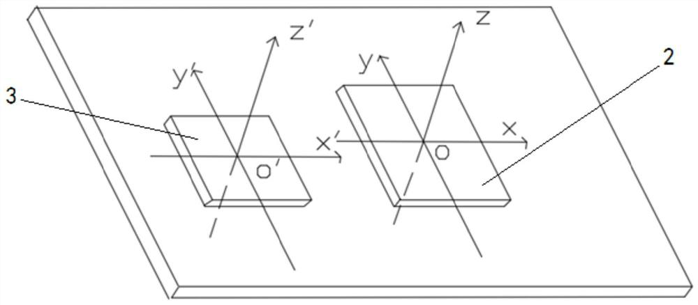
[0105] see figure 2 , image 3 and Figure 5 , the embodiment of the present invention also provides an image imaging shake compensation system that runs the above-mentioned image imaging shake compensation method, including a main control module 1, and an image acquisition device 2 and a sensor that are respectively connected to the main control module 1 in data module 3;

[0106] The image acquisition device 2 is used to acquire the moving image of the target object 0 and send it to the main control module 1;

[0107] The sensor module 3 is used to collect the vibration acceleration data of the image acquisition device 2 and send it to the main control module 1;

[0108] The main control module 1 is used to calculate the image displacement of the target object 0 according to the moving image; it is also used to calculate the shake displacement of the image acquisition device 2 according to the shake acceleration data; The correction data of the target object 0 is obtain...

Embodiment 3

[0120] An embodiment of the present invention also provides an image imaging shake compensation device, which includes the above image imaging shake compensation device system, or runs the above image imaging shake compensation method.

[0121] The embodiment of the present invention provides an image imaging shake compensation equipment system and equipment. A gravity sensor is installed at a parallel position of the camera assembly, and the shake acceleration data of the camera assembly is obtained in real time through the gravity sensor; the SOC chip is used as the main control module 1, and its The operation function is to perform logical operation on the collected moving images and shaking acceleration data to obtain the corrected coordinates of the target object 0. The present invention realizes the effective detection of the jitter displacement of the target object by adding a simple and low-cost gravity sensor, adopts a highly integrated circuit and a fully functional S...


PUM


Abstract

The invention relates to the technical field of image processing, and provides an image imaging jitter compensation method, system and device, and the method comprises the steps: installing a gravitysensor at a parallel position of a camera assembly, and obtaining the jitter acceleration data of the camera assembly in real time through the gravity sensor; adopting an SOC chip as a main control module, and utilizing the operation function of the SOC chip to perform logic operation on collected moving images and jitter acceleration data to obtain correction coordinates of a target object. According to the invention, the simple and low-cost gravity sensor is additionally arranged, so the shaking displacement of the target object is effectively detected; the SOC chip with highly integrated circuits and comprehensive functions is adopted to perform data operation, and direct output from moving images and jitter acceleration data to correction coordinates is realized, so the effective compensation of jitter displacement of a target object is realized on the basis of ultra-low manufacturing cost, and the accuracy of image imaging is greatly improved.

Description

technical field [0001] The present invention relates to the technical field of image processing, in particular to an image imaging shake compensation method, system and equipment. Background technique [0002] With the progress of the times, video surveillance, as an important evidence for security protection systems and event tracing, has gradually become popular in all walks of life. When acquiring images, how to improve the accuracy of image imaging has also become a challenge. [0003] Due to the consideration of driving safety and the development needs of autonomous driving, video surveillance is basically popularized in the vehicle field. However, due to the vertical vibration of the car during the movement, the vehicle video surveillance equipment (vehicle camera) when collecting images There will also be jitter, which will cause the position of the imaging object in the collected image to shift accordingly, resulting in the problems of blurred, low-definition, and p...

Claims


Application Information

Patent Timeline
IPC IPC(8): H04N5/232
CPCH04N23/681
Inventor 蒋才科
Owner FORYOU GENERAL ELECTRONICS
Why Eureka
Try Eureka