
Heat dissipation structure of condenser

A heat dissipation structure and condenser technology, applied in cooling/ventilation/heating transformation, indirect heat exchangers, lighting and heating equipment, etc., can solve the problem of reducing service life, unable to meet the heat dissipation requirements of high heat flux electronic components, and concentrating heat sources and other issues to achieve the effect of improving the overall efficiency and improving the overall cooling efficiency

Active Publication Date: 2020-09-01
LDC PRECISION ENG
View PDF19 Cites 0 Cited by
  • Summary
  • Abstract
  • Description
  • Claims
  • Application Information

AI Technical Summary

Problems solved by technology

The direct air cooling technology currently widely used can no longer meet the cooling needs of many electronic components with high heat flux, and other solutions must be sought
[0003] In the existing technology, in addition to the air cooling technology, it has the purpose of using the liquid-gas conversion of the liquid to achieve the purpose of heat dissipation. This technology provides two sets of heat spreaders and two sets of connected pipes. One set of heat spreaders is used to Evaporate to take away the absorbed heat, and another set of equalizers is used for condensation (ie condenser) to cool down and return to the circuit that outputs cooling liquid for heat dissipation circulation, and the pressures in the two sets of equalizers are different, so the liquid can Automatic back-and-forth transportation, but the interior of the heat spreader is mostly designed with simple fins or flow channels for the liquid to circulate in it, which can easily cause the heat source to be concentrated in a specific position, so excessive evaporation will occur in a specific position The state of low water level and high temperature in some places not only leads to unstable and uneven heat dissipation, but also shortens the service life more quickly

Method used


Image

  • Heat dissipation structure of condenser
  • Heat dissipation structure of condenser
  • Heat dissipation structure of condenser

Examples


Embodiment Construction

[0049] The technical solutions in the embodiments of the present invention are clearly and completely described below in conjunction with the drawings in the embodiments of the present invention. In the following description, a lot of specific details are set forth in order to fully understand the present invention, but the present invention can also be implemented in other ways different from those described here, and those skilled in the art can do it without departing from the meaning of the present invention. By analogy, the present invention is therefore not limited to the specific examples disclosed below.

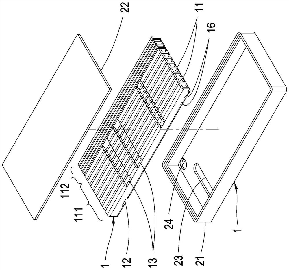
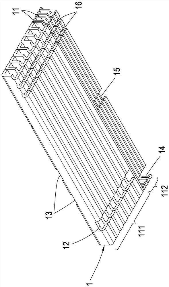
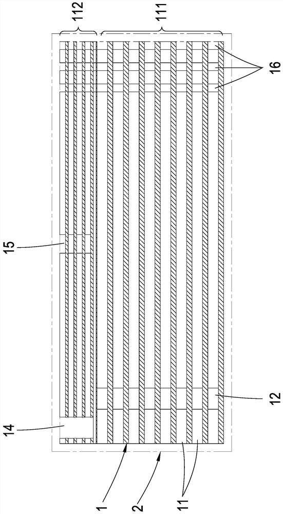
[0050] see Figure 1~Figure 4 , are respectively the overall or partial three-dimensional schematic diagram and the internal structure cross-sectional schematic diagram of the heat dissipation structure of the condenser of the present invention, as shown in the figure, at least including a heat exchange module 1 and a shell 2;

[0051] Wherein, the heat exchange mod...


PUM


Abstract

The invention discloses a heat dissipation structure of a condenser. The heat dissipation structure comprises a heat exchange module and a shell, a large number of inner channels are arranged in the heat exchange module, and each inner channel is provided with a high-pressure area and a low-pressure area. A cold air source is arranged beside the low-pressure area, the high-pressure area is provided with at least one water inlet through hole, and at least one water outlet through hole is formed at the position, corresponding to the water inlet through hole, below the low-pressure area. A plurality of connecting channels are formed in the inner channel far away from the water inlet through hole and the water outlet through hole, the high-pressure area and the low-pressure area are communicated through the connecting channels, the heat exchange module is placed in the shell, and the entering steam passes through the connecting channels in the longest path, so that the steam can flow and circulate in the heat exchange module with the largest contact area, and the overall heat dissipation benefit is improved.

Description

technical field [0001] The invention relates to a heat dissipation structure of a condenser, which is used to convert heat energy into gas and liquid inside to achieve heat dissipation effect, and is suitable for matching with an evaporator as an electronic component for heat dissipation. Background technique [0002] In recent years, the calorific value of electronic components has been increasing rapidly with the improvement of semiconductor technology; how to improve the heat dissipation capacity of electronic components and maintain the normal operation of components has become a very important engineering topic. The direct air cooling technology widely used at present can no longer meet the heat dissipation requirements of many electronic components with high heat flux, and other solutions must be sought. [0003] In the existing technology, in addition to the air cooling technology, it has the purpose of using the liquid-gas conversion of the liquid to achieve the purp...

Claims


Application Information

Patent Timeline
Patent Type & Authority Applications(China)
IPC IPC(8): H05K7/20F28D21/00
CPCH05K7/20318F28D21/00F28D2021/0029
Inventor 徐启峰梁政仁
Owner LDC PRECISION ENG
Learn More