Quick catalyst coating device suitable for ceramic filter pipe

A catalyst device and catalyst technology, which are applied to devices and coatings for coating liquid on the surface, can solve the problems of long processing time and uneven catalyst loading, and achieve short running time, thorough coating and high utilization rate. Effect

Inactive Publication Date: 2020-09-04
安徽紫朔环境工程技术有限公司
View PDF0 Cites 3 Cited by
  • Summary
  • Abstract
  • Description
  • Claims
  • Application Information

AI Technical Summary

Problems solved by technology

At present, the impregnation method is the main method for supporting catalysts, which requires a long treatment time, and the catalyst loading is easily uneven.

Method used


Image

  • Quick catalyst coating device suitable for ceramic filter pipe

Examples


Embodiment Construction

[0015] Below with reference to the accompanying drawings, through the description of the embodiments, the specific embodiments of the present invention, such as the shape, structure, mutual position and connection relationship between each part, the role and working principle of each part, etc. detailed instructions.

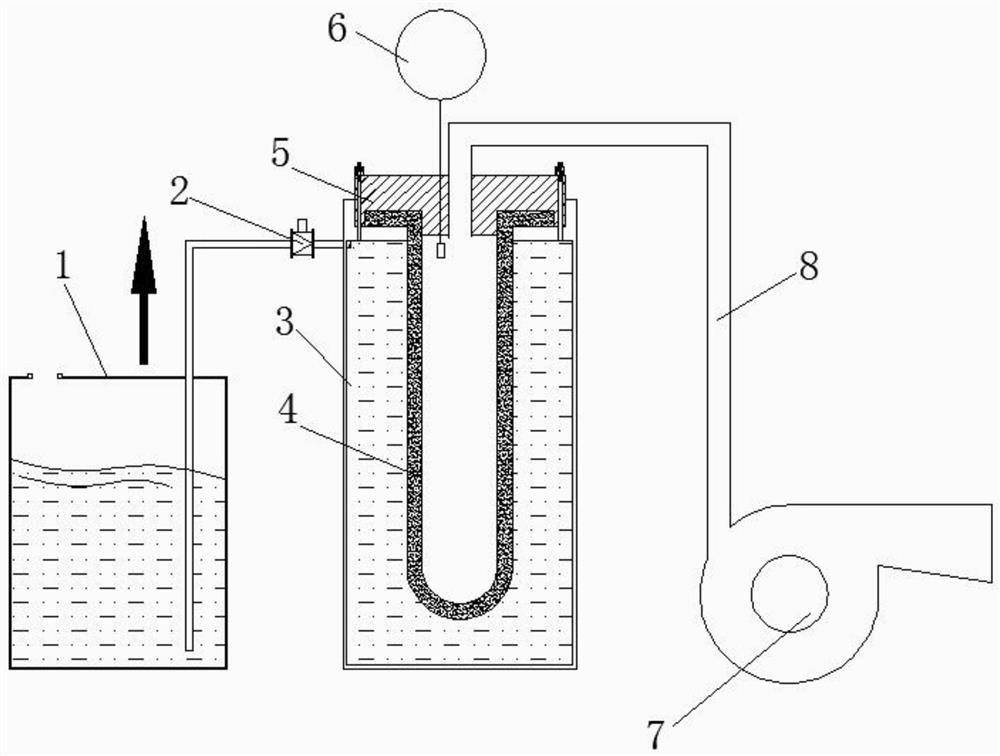
[0016] Such as figure 1 As shown, the rapid coating catalyst device suitable for ceramic filter tubes includes a catalyst stock solution barrel 1, a check valve 2, a vacuum chamber 3 and a vacuum suction pump 7, and the catalyst stock solution barrel 1 is connected to the vacuum chamber 3 through a delivery pipeline. A one-way valve 2 is set on the delivery pipeline, and the one-way valve 2 makes the catalyst stock solution only flow from the barrel of the stock solution to the vacuum chamber without reverse flow. It is fixed on the top of the vacuum chamber 3 by bolts, the ceramic filter tube 4 is fixed on the top cover 5, the top cover 5 is connected with the...


PUM


Abstract

The invention discloses a quick catalyst coating device suitable for a ceramic filter pipe, and belongs to the field of filter pipes. The quick catalyst coating device suitable for the ceramic filterpipe comprises a catalyst stock solution barrel connected with a vacuum chamber through a pipeline, a one-way valve is arranged on the pipeline, the ceramic filter pipe is arranged in the vacuum chamber, a top cover is arranged at the top of the vacuum chamber and fixed at the top of the vacuum chamber through bolts, the ceramic filter pipe is fixed on the top cover, the top cover is connected with a vacuum suction pump through a suction pipeline, and the catalyst stock solution barrel is filled with catalyst stock solution. According to the quick catalyst coating device suitable for the ceramic filter pipe, a vacuum suction technology and an automatic control technology are combined, quick coating of the ceramic filter pipe can be achieved, a liquid level monitoring device installed in the ceramic filter pipe is connected with a control system so that automatic start and stop of the coating of the ceramic filter pipe can be realized, and the whole device is high in catalyst utilization rate, thorough in the coating and short in operation time, and can be used for a mass production process of ceramic catalytic filter pipes.

Description

technical field [0001] The invention relates to the field of filter tubes, in particular to a rapid catalyst coating device suitable for ceramic filter tubes. Background technique [0002] In recent years, with the improvement of industrial flue gas emission requirements, new treatment technologies have also been continuously innovated, among which ceramic catalytic filter tube technology has gradually become a key development direction in the field of flue gas denitrification and dust removal. Ceramic catalytic filter is mainly used for denitrification and dust removal of industrial flue gas. The interior is an intricate porous structure, which has the characteristics of high denitrification efficiency and strong dust removal ability. . At present, the impregnation method is the main method for supporting catalysts, which requires a long treatment time, and the catalyst loading is easily uneven. [0003] Therefore, in order to reduce the production time of ceramic filter ...

Claims


Application Information

Patent Timeline
IPC IPC(8): B05C3/09B05C11/10
CPCB05C3/09B05C11/101
Inventor 项泽顺张矿王洪明孟祥民徐淮北崔等
Owner 安徽紫朔环境工程技术有限公司
Why Eureka
Try Eureka